Table of Contents
Advertisement
Quick Links
Advertisement
Table of Contents

Summary of Contents for RePower NIUESS
- Page 1 Energy Storage System User manual 深圳市瑞能时代科技有限公司 RePower Technology Co., Ltd...
- Page 2 Preface The manual is intended to provide detailed information of product information, installation, application, trouble shooting, precautions and maintenance of the energy storage system.. Please read this manual carefully and follow all safety precautions seriously before any moving, installation, operation and maintenance to ensure correct use and high performance of operation on the machine.
-
Page 3: Table Of Contents
Energy storage integrated machine Content Content Preface................................ i Content..............................ii Safety precautions..........................1 Warning signs..........................1 Safety guide..........................1 1.2.1 Transportation and installation.................... 4 1.2.2 Grid-tied operation......................5 1.2.3 Maintenance and replacement.....................5 1.2.4 What to do after scrapping....................5 Product overview..........................6 Energy storage system.........................6 Product appearance........................ - Page 4 Energy storage integrated machine Content 5.3.2 Instruction for setup parameter..................27 5.3.3 Inverter data display......................29 Fault code............................30...
-
Page 5: Safety Precautions
Energy storage integrated machine Safety precautions 1. Safety precautions Energy storage integrated machines are designed and tested strictly in accordance with relevant international safety standards. As an electrical and electronic device, all relevant safety regulations must be strictly complied during installation, operation, and maintenance. Incorrect use or misuse may result in: •... -
Page 6: Warning Signs
Energy storage integrated machine Safety precautions 1.1 Warning signs Warning signs are used to warn you about the conditions that may cause severe injury or damage to the device. They instruct you to exercise caution to prevent danger. The following table describes the warning signs used in this manual. -
Page 7: Safety Guide
Energy storage integrated machine Safety precautions 1.2 Safety guide •After receiving this product, first confirm the product package is intact. If any question, contact the logistic company or local distributor immediately. •The installation and operation of the machine must be carried out by professional technicians who have received professional training, and thoroughly familiar with all the contents in this manual and the safety requirements of the electrical system. - Page 8 Energy storage integrated machine Safety precautions Single PV string cannot connect to muti-inverters One battery bank cannot be connected to muti-inverters Inverters do not support three-phase operation...
- Page 9 Energy storage integrated machine Safety precautions Back-up cannot connect in parallel On-grid or back-up side cannot connect any ac generator...
-
Page 10: Transportation And Installation
Energy storage integrated machine Safety precautions 1.2.1 Transportation and installation . Keep the package and unit complete, dry and clean during storage and transportation. This machine Is heavy. Please remove and Install It with at least two people. , lb ensure the normal and safe operation of the energy storage integrated machine and avoid personal injury, please select proper handling and installation tools, and take mechanical protection measures to protect personal safety such as wearing smashing shoes, coverall and so on. -
Page 11: Grid-Tied Operation
Energy storage integrated machine Safety precautions 1.2.2 Grid-tied operation * Only qualified electricians are allowed to operate the machine under the permission of local power departments. *All electrical connections must meet the electrical standards of the countries/regions in which the project is located. *Ensure reliable installation and electrical connection before operation. -
Page 12: Product Overview
Energy storage integrated machine Product overview 2 Product overview This chapter mainly describes the appearance, packaging accessories and other information of energy storage integrated machines. 2.1 Energy storage system Figure 2.1 Energy storage system Symbol Description PV module Battery Energy storage integrated machine Public grid Load... -
Page 13: Product Appearance
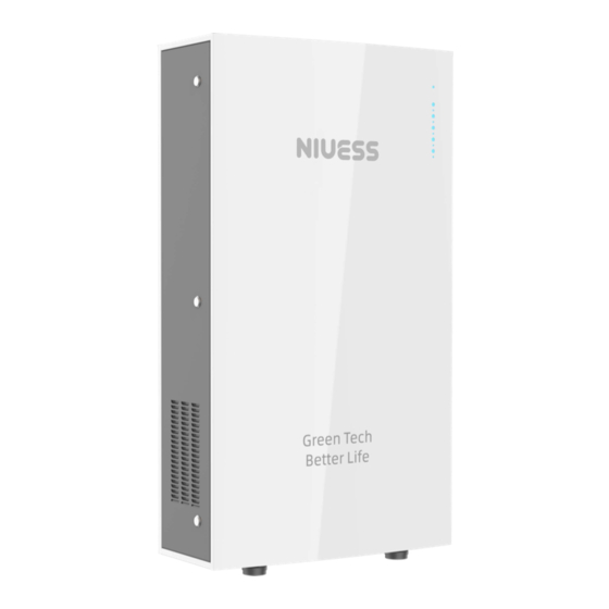
Energy storage integrated machine Product overview 2.2 Product appearance Figure 2.2 Appearance of RESS 5000-A of the all-in-one energy storage machine Figure. 2.3 Appearance of inverter module of the all-in-one energy storage machine... -
Page 14: Key Component Description
Energy storage integrated machine Product overview Figure. 2.4 Appearance of battery module of the all-in-one energy storage machine 2.2.1 Key component description Figure 2.3 Appearance diagram of inverter module for energy storage integrated machine Name Description LCD interface LCD connection terminal COMM/DRM COMM/DRM communication port Cooling fan... -
Page 15: Products Modules
Energy storage integrated machine Product overview 2.3 Products modules Product name Model Rated output power (W) Single phase (L, N, and PE) Single-phase energy storage 3000 integrated machine Note: Technical parameters of the energy storage integrated machine refers to appendix. 2.4 Dimensions and weight Figure 2.4 Dimensions of the energy storage integrated machine Dimension and net weight of the energy storage integrated machine... -
Page 16: Storage Of The Energy Storage Integrated Machine
Energy storage integrated machine Storage of the energy storage integrated machine 3 Storage of the energy storage integrated machine If the machine is not put into use immediately, the storage of the machine should meet the following requirements: • Do not remove the outer packing. •... -
Page 17: Installation
Energy storage integrated machine Installation 4 Installation 4.1 Unpacking confirmation Before unpacking, check carefully whether the product information in the order is consistent with that on the nameplate of the package box, and whether the product package is intact. If there is any question, please contact the supplier timely. - Page 18 Energy storage integrated machine Installation Delivery list of 3 KW/5 KW energy storage integrated machine name quantity remarks 3 kW / 5 kW energy storage integrated machine cabinet communication connector RS485 communication connector DRMO communication connector RS485 Communication link RJ45 reticle Power cable of the battery energy storage integrated machine User manual M5*14 hex assembling bolts...
-
Page 19: Preparation Before Installation
Energy storage integrated machine Installation 4.2 Preparation before installation 4.2.1 Installation tools -13-... - Page 20 Energy storage integrated machine Installation Figure 4.2 Installation spacing(unit : IN) In order to ensure good ventilation of the energy storage integrated machine, please reserve enough installation spacing around the machine during installation. -14-...
-
Page 21: Electrical Connection
Energy storage integrated machine Installation Note: Should not be installed in direct sunlight, rain, snow cover and other places. 4.3 Electrical connection This section introduces the detailed contents and safety precautions related to electrical connection. Figure 4.3 Connection diagram of the system -15-... - Page 22 Energy storage integrated machine Installation Name PV string PV side DC switch (DC600V, C32A, 2P) Energy storage inverter(or Hybrid Inverter ) AC switch (AC250V,C40A, 2P) Digital meter Public grid Load *Electrical connection must be carried out by professional technicians as wrong operation may cause damage to the device, physical injuries or even death during system operation.
-
Page 23: Battery Connection
Energy storage integrated machine Installation 4.3.1 Battery connection Name Mark Detail description Ground Ground connection Power on key. Touch the button to turn it on. POWER On/Off button Press for more than 6 seconds and then release the button to shut down. SOC LED Shows the battery SOC。... - Page 24 Energy storage integrated machine Installation • Ensure that the maximum open circuit voltage of each PV string is not higher than the maximum input voltage of the energy storage integrated machine under any circumstances. • It is forbidden to connect the PE wire (ground wire) to the positive and negative poles of the PV strings, otherwise it will cause damage to the energy storage integrated machine.
-
Page 25: Grid And Load Connection
Energy storage integrated machine Installation 4.3.2 Grid and load connection Only qualified AC transmission cables under the local electrical safety laws and regulations and comply with the technical parameters of this manual are allowed to connect to the energy storage integrated machines. Please install an AC breaker between the battery and the energy storage integrated machine (250 A-30 A recommend). -
Page 26: Definition Of Can Interface Pin In The Battery
Energy storage integrated machine Installation 4.4.3 Definition of CAN interface pin in the battery Figure 4.7 CAN communication — — — — — CANH CANL 4.4.4 Definition of CAN2 interface pm in the energy storage inverter Figure 4.8 CAN2 communication wiring diagram CANH1 CANL1 -20-... -
Page 27: Rs-485 Communication Connection
Energy storage integrated machine Installation 4.4.5 RS-4S5 communication connection The RS-485 communication of the energy storage integrated machine is used for upper PC monitoring, and monitoring of our company's WIFI and GPRS communication. It can realize local monitoring, remote monitoring as well as mobile APP monitoring. The RS-485 communication interface of our energy storage integrated machine carries three-channel communications. - Page 28 Energy storage integrated machine Installation Table 3-4 RS-485 1/2 communication interface definition Port no. Port definition RS1U85+ RS1-485- RS2U85+ +5VDC RS2-485- Figure 4.10 RS485 3 standard connector Table 3-5 RS-485 3 communication interface definition Connector pin of the energy storage Pin definition integrated machine communication +5VDC...
- Page 29 Energy storage integrated machine Installation 4.4.6 DRMO/COMW/Battery_ TEMP/CT communication connection Figure 4.11 communication connector Table 3-6 DRMO/COMM communication connecter Pins instruction Connector pin of the energy storage Pin definition integrated machine DRM1/5 DRM2/6 DRM3/7 BAT_NTC1 BAT_NTC2 DRM4/8 Detail instructions: 1 ・ Pin1 Pin2 Pin3 Pin8...
-
Page 30: Lcd Operation Instructions
Energy storage integrated machine LCD operation instructions 5 LCD operation instructions 5.1 Instruction for main page After the machine enters the working state, the main page displays the energy flow diagram according to machine state as shown in figure 5.1. Figure 5.1 Icon instruction Icon Instruction... - Page 31 Energy storage integrated machine LCD operation instructions -24-...
-
Page 32: Display Menu
Energy storage integrated machine LCD operation instructions 5.2 Display menu Icon name Parameter name PV1 voltage PV2 voltage PV1 current PV2 current PV1 power PV information PV2 power Daily generation Monthly generation Annual generation Total generation operation Energy storage integrated Alarm machine information Power curve... -
Page 33: Parameter Setup Of The Energy Storage Integrated Machine
Energy storage integrated machine LCD operation instructions Icon name Parameter name Battery current Battery power Battery temperature Battery SOC Load voltage Load current Active power Apparent power Load information Daily consumption Monthly consumption Annual consumption Total consumption 5.3 Parameter setup of the energy storage integrated machine 5.3.1 Parameter classification page The parameter classification page has five menus, corresponding to five groups of setup parameters. - Page 34 Energy storage integrated machine LCD operation instructions 5.3.2 Instruction for setup parameter Name of Name of setup Instruction/Range of the set value parameter Menu parameter group PV connection PV connection mode: PV parameter Connection mode mode: (0: Independent; 1: Parallel) PF setup PF setup, range: -1.000-1.000 Grid...
- Page 35 Energy storage integrated machine LCD operation instructions Name of Name of setup Instruction/Range of the set value paramete r Menu parameter group Discharge time End time of discharge time period period 1 ends: 1, range: 0-23:59 Charge time period Start time of charge time period Charge time period 2 starts: range: 0-23:59...
- Page 36 Energy storage integrated machine LCD operation instructions 5.3.3 Inverter data display Data name Instruction/Range of the set value Working mode Working mode of the inverter Temperature Temperature in the inverter Device type Production data Auxiliary DSP software version no. Product SN Grid-tied standard Hardware version CPU1 software version...
- Page 37 Energy storage integrated machine Fault code 6 Fault code This chapter mainly introduces faults alarms and fault codes for users to quickly identify the machine fault. Table 6-1 Fault code for the energy storage integrated machine Fault code Description Analysis Ac voltage highl Grid voltage is higher than protection point 1 Ac voltage high2...
- Page 38 Energy storage integrated machine Fault code Fault code Description Analysis PV1 voltage high PV1 overvoltage PV1 voltage low PV1 undervoltage PV2 voltage high PV2 overvoltage PV2 voltage low PV2 undervoltage PV1 over current PV1 overcurrent PV2 over current PV2 overcurrent RTC error RTC error Eeprom error...
Need help?
Do you have a question about the NIUESS and is the answer not in the manual?
Questions and answers