Advertisement
Available languages
Available languages
Quick Links
Introduction:
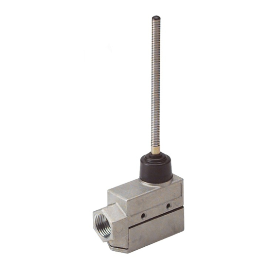
Back-up alarm activation switches are designed for use primarily on off-road
vehicles that do not have a reversing light circuit or where routing the alarm's
wiring into the reversing light circuit is not feasible. These switches are
installed adjacent to the gear shift lever so that shifting into reverse will move
the switch actuator arm, activating the back-up alarm.
IMPORTANT!
Read all instructions before installing and using. Installer: This manual must be
delivered to the end user.
WARNING!
Failure to install or use this product according to manufacturers recommendations may result in property
damage, serious bodily/personal injury, and/or death to you and those you are seeking to protect!
Do not install and/or operate this safety product unless you have read and understand the safety
information contained in this manual.
1. Proper installation combined with operator training in the use, care, and maintenance of emergency warning devices are
essential to ensure the safety of you and those you are trying to protect.
2. Exercise caution when working with live electrical connections.
3. This product must be properly grounded. Inadequate grounding and/or shorting of electrical connections can cause high
current arcing, which can cause personal injury and/or severe vehicle damage, including fire.
4. Proper placement and installation are vital to the performance of this warning device. Install this product so that output
performance of the system is maximized and the controls are placed within convenient reach of the operator so that s/he can
operate the system without losing eye contact with the roadway.
5. It is the responsibility of the vehicle operator to ensure during use that all features of this product work correctly. In use, the
vehicle operator should ensure the projection of the warning signal is not blocked by vehicle components (i.e., open trunks
or compartment doors), people, vehicles, or other obstructions.
6. The use of this or any other warning device does not ensure all drivers can or will observe or react to a warning signal.
Never take the right-of-way for granted. It is your responsibility to be sure you can proceed safely before entering an
intersection, driving against traffic, responding at a high rate of speed, walking on or around traffic lanes.
7. This equipment is intended for use by authorized personnel only. The user is responsible for understanding and obeying
all laws regarding warning signal devices. Therefore, the user should check all applicable city, state, and federal laws and
regulations. The manufacturer assumes no liability for any loss resulting from the use of this warning device.
8. This product contains high intensity LEDs, staring directly into these lights could result in temporary and/or permanent vision
impairment.
Back-Up Alarms must be tested each day prior to vehicle operation. A record of this test must be re-
corded in the vehicle maintenance file.
920-0415-00 Rev B
Installation and Operation Instructions
Mechanical Switch
Page 1 of 3
Advertisement

Summary of Contents for Ecco SW15
- Page 1 Installation and Operation Instructions Mechanical Switch Introduction: Back-up alarm activation switches are designed for use primarily on off-road vehicles that do not have a reversing light circuit or where routing the alarm’s wiring into the reversing light circuit is not feasible. These switches are installed adjacent to the gear shift lever so that shifting into reverse will move the switch actuator arm, activating the back-up alarm.
-
Page 2: Installation
IMPORTANT! This unit is a safety device, and must be connected to it’s own seperate, fused power point to assure it’s continued operation should any other electrical accessory fail. Installation: Install the switch adjacent to the gear shift lever so that shifting into reverse will move the switch actuator arm sufficiently to make electrical contact. - Page 3 Manufacturer Limited Warranty and Limitation of Liability: Manufacturer warrants that on the date of purchase this product will conform to Manufacturer’s specifications for this product (which are available from the Manufacturer upon request), and Manufacturer further warrants that this product is free from defects in materials and workmanship. This Limited Warranty extends for twenty-four (24) months from the date of manufacture.
- Page 4 Instrucciones de instalación y uso Interruptor mecánico Introducción: Los interruptores de activación de alarmas de retroceso están diseñados para uso fundamentalmente en vehículos fuera de carretera que no tengan un circuito de luces de marcha atrás o donde no sea factible enrutar los cables de la alarma al circuito de luces de marcha atrás.
-
Page 5: Instalación
¡IMPORTANTE! Esta unidad es un dispositivo de seguridad y debe conectarse a su propia alimentación con fusible, para garantizar una operación continua en el caso de que falle cualquier otro accesorio eléctrico. Instalación: Instale el interruptor adyacente a la palanca de cambios de manera que al poner marcha atrás el brazo accionador del interruptor se mueva lo suficiente para hacer contacto eléctrico. - Page 6 Limitación de responsabilidad y garantía limitada del fabricante: El fabricante garantiza que al momento de la compra, este producto cumple con las especificaciones del fabricante para el mismo (disponibles a pedido). El fabricante garantiza además que el presente producto está libre de defectos en sus materiales y en su fabricación. Esta garantía limitada se extiende durante veinticuatro (24) meses a partir de la fecha de fabricación.
- Page 7 Instructions d’installation et d’utilisation Interrupteur mécanique Introduction : Les commutateurs d’activation de l’avertisseur sonore de recul sont essentiellement conçus pour les véhicules hors route qui n’ont pas de circuit de feux de recul ou lorsque le passage des câbles de l’alarme dans ce circuit est impossible.
- Page 8 IMPORTANT! Cette unité est un outil de sécurité et doit être reliée à son propre point d’impulsion distinct muni d’un fusible pour assurer son fonctionnement continu au cas où un autre accessoire électrique tomberait en panne. Installation : Installez le commutateur à côté du levier de vitesse de sorte que le passage en marche arrière déplace suffisamment le bras d’actionnement du commutateur pour provoquer un contact électrique.
- Page 9 Garantie limitée et limitation de responsabilité du fabricant : Le fabricant garantit qu’à la date d’achat ce produit sera conforme aux caractéristiques techniques définies par ses soins (disponibles sur demande) et qu’il est exempt de vices de fabrication et de main-d’œuvre. La présente garantie limitée est valable vingt-quatre (24) mois à compter de la date de fabrication. D’autres garanties peuvent s’appliquer. Pour plus d’informations, contactez le fabricant.
Need help?
Do you have a question about the SW15 and is the answer not in the manual?
Questions and answers