Table of Contents
Advertisement
Advertisement
Table of Contents

Summary of Contents for Zebra-Tech D-Opto
- Page 1 D-Opto Logger Dissolved Oxygen Logger Operation Manual...
-
Page 2: Table Of Contents
Optical Sensor Technology..............3 Software ......................4 Installation ....................4 Operation....................4 Operation .......................9 Installation ....................9 Sealing the D-Opto Logger ..............9 Logging Endurance ................9 Routine Maintenance................10 Calibration ....................11 Appendix 1: Data File Format ..............13 Appendix 2: Communication Cable Wiring Scheme ........14 Appendix 3: LED flash sequence codes ............15 Appendix 4: Trouble shooting ..............16... -
Page 3: Introduction
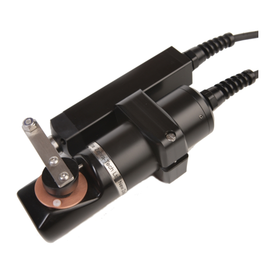
The D-Opto Logger uses a field-proven solid-state optical sensing system to measure dissolved oxygen that is highly stable over long periods of time, even in harsh conditions. The data is stored onboard in non-volatile memory. The D-Opto Logger is setup, and data offloaded using simple Windows based software, supplied with the instrument. -
Page 4: Software
• Enables the user to communicate with the D-Opto Logger via a computer; • Is used to setup the D-Opto Logger prior to deployment; • Is used to download data from the D-Opto Logger to the PC after retrieval. 2.1 Installation The D-Opto Logger is supplied with a software CD that contains the file “Install... - Page 5 D-OptoLogger Operation Manual Figure 1: D-OptoLog serial port selection window. With most computers the D-Opto Logger will be connected to com port number 1. However, if the D-Opto Logger is connected to the computer’s USB port via a USB to serial converter, the port number will probably be either com port 4 or 5.
- Page 6 The main window displays current dissolved oxygen (% saturation and PPM) and temperature (°C) data, and is updated approximately once every second. The serial number displayed is factory set and is unique to each D-Opto Logger. It corresponds to the number displayed on the outside of the D-Opto Logger housing.
- Page 7 D-OptoLogger Operation Manual content of fully aerated water (Figure 5). It will accept either altitude (m) or barometric pressure (mBar). By pressing the “Restore defaults” button, the original factory calibration values are reinstated by the D-Opto Logger. Figure 4: D-OptoLogger Calibration window.
- Page 8 Zebra-Tech Ltd D-OptoLogger Operation Manual Figure 5: Pressure Correction Calculator...
-
Page 9: Operation
D-Opto Logger is suspended solely from the eyelet swivel. 3.2 Sealing the D-Opto Logger The D-Opto Logger end cap features a dual “O” ring sealing system. It is essential that these “O” rings are properly serviced and maintained; otherwise moisture may penetrate the housing. -
Page 10: Routine Maintenance
7.0 volts. If this occurs whilst the D-Opto Logger is in logging mode, the last set of data values in the data file will be set to zero, and the D-Opto Logger enters a low power sleep mode, with no further data values being logged. -
Page 11: Calibration
Under normal operating conditions, the D-Opto Logger should only require infrequent calibration. Calibration of the D-Opto Logger is a simple operation that can be carried out in the field. Due to the measurement principle of the D-Opto Logger, performing air calibrations are not advisable. - Page 12 Zebra-Tech Ltd D-OptoLogger Operation Manual the D-Opto Logger is installed at a field site at 435 meters above sea level, and a fully aerated reference solution is prepared on site, the actual dissolved oxygen percent saturation is calculated at 95%.
-
Page 13: Appendix 1: Data File Format
Zebra-Tech Ltd D-OptoLogger Operation Manual Appendix 1: Data File Format Data Field Number Description Year Month Hour Minute Second Battery voltage Temperature (Degrees C) Dissolved Oxygen (%) Dissolved Oxygen (ppm) -
Page 14: Appendix 2: Communication Cable Wiring Scheme
Zebra-Tech Ltd D-OptoLogger Operation Manual Appendix 2: Communication Cable Wiring Scheme... -
Page 15: Appendix 3: Led Flash Sequence Codes
Zebra-Tech Ltd D-OptoLogger Operation Manual Appendix 3: LED flash sequence codes Inside the D-OptoLogger housing, next to the battery and communication socket, there is an LED. The LED flashes according to the current status of the D- OptoLogger. The interval between the flashing sequence may be up to 8 seconds. -
Page 16: Appendix 4: Trouble Shooting
• Track down the source of noise; this could be a nearby pump or other motor. • If the D-Opto Logger is being bench tested in a small container of water, noise can be caused by a lack of suitable earthing. Place a grounding wire from the water to the D-Opto Logger power ground. -
Page 17: Appendix 5: Specifications
Zebra-Tech Ltd D-OptoLogger Operation Manual Appendix 5: Specifications Physical Dimensions 200mm long x 50mm diameter Accuracy Temperature: +/- 0.1 deg C 1% of reading or 0.02 PPM, which ever is greater Resolution Temperature: 00.01 Deg C DO saturation: 000.01% PPM: 00.001 ppm... -
Page 18: Appendix 6: Pressure Correction Chart
Zebra-Tech Ltd D-OptoLogger Operation Manual Appendix 6: Pressure correction chart Dissolved oxygen % saturation values of air saturated fresh water, corrected for atmospheric pressure. Altitude Altitude Barometric pressure (feet) (mBar) % Saturation 1013 1003 1126 1413 1703 1995 2290 2587... -
Page 19: Appendix 7: Useful Conversions
Zebra-Tech Ltd D-OptoLogger Operation Manual Appendix 7: Useful Conversions Convert from Calculation mBar Multiply by 10 inHg mBar Multiply by 33.85 Feet Meters Multiply by 0.3048 ° Centigrade Fahrenheit (9/5 °C)+32... - Page 20 Zebra-Tech Ltd D-OptoLogger Operation Manual Zebra-Tech Ltd Contact Details PO Box 1668 Nelson New Zealand Tel: (0064)03 5471590 Fax: (0064)03 5471598 Email: enquiry@zebra-tech.co.nz...
Need help?
Do you have a question about the D-Opto and is the answer not in the manual?
Questions and answers