
Summary of Contents for SPH Engineering Amass XT30U-F
- Page 1 Industrial Solutions Data Logger User Manual industrial.ugcs.com July 2019 Revision 1...
- Page 2 Data Logger User Manual Revision History Revision Date Description 27.07.2019 • Initial release Copyright © 2019, SPH Engineering Revision 1 • July 2019...
-
Page 3: Table Of Contents
........24 Copyright © 2019, SPH Engineering... -
Page 4: Description
• 12 V power output with switch-off from −25°C to +85°C function for payload connecting Applications • Custom payload integration with drone • Using drones in adverse environment • Advanced UAV flight control scenarios Copyright © 2019, SPH Engineering Revision 1 • July 2019... -
Page 5: In The Box
Figure 1•1 — Interaction diagram In the Box • 1× Data Logger unit • 1× Power cable (Amass XT30U-M — Amass XT30U-F) • 1× Cable to flight controller (Lemo FGG.0B.303 — 4-pin 2.54 mm pitch receptacle) Device Overview Main device elements are illustrated below. - Page 6 Indicates the presence of core power UART1 Communicates with UART-based payloads (see UART1) Power LED (green) Indicates the presence of input power UART0 Communicates with the flight controller (see UART0) Copyright © 2019, SPH Engineering Revision 1 • July 2019...
-
Page 7: Specifications
1 (with 5 V power output) Wi-Fi Dual-band 802.11ac Bluetooth 4.2 with BLE support Ethernet 10/100 Mbit Mechanical Dimensions (L × W × H) 109 × 69 × 34 mm Weight 180 g Copyright © 2019, SPH Engineering Revision 1 • July 2019... -
Page 8: Connectors
3 • Connectors Data Logger User Manual 3 • Connectors Power Input • Mating connector on the cable side: Amass XT30U-F • Voltage range: 15 V to 36 V • Protected against reverse polarity Pinout (device side) Name Description Power supply voltage... -
Page 9: I²C
Dedicated to communicating with the payload equipped with I²C interface. • Mating connector on the cable side: Lemo FGG.0B.304 • Logic level: 3.3 V • Isolated from CPU • ESD-protected Copyright © 2019, SPH Engineering Revision 1 • July 2019... -
Page 10: Ethernet
• Mating connector on the cable side: RJ-45 • Bitrate: 10/100 Mbit Antenna • Mating connector on the cable side: Reverse-Polarity (RP) SMA Male • Frequency: combined 2.4 and 5 GHz Copyright © 2019, SPH Engineering Revision 1 • July 2019... -
Page 11: Installation
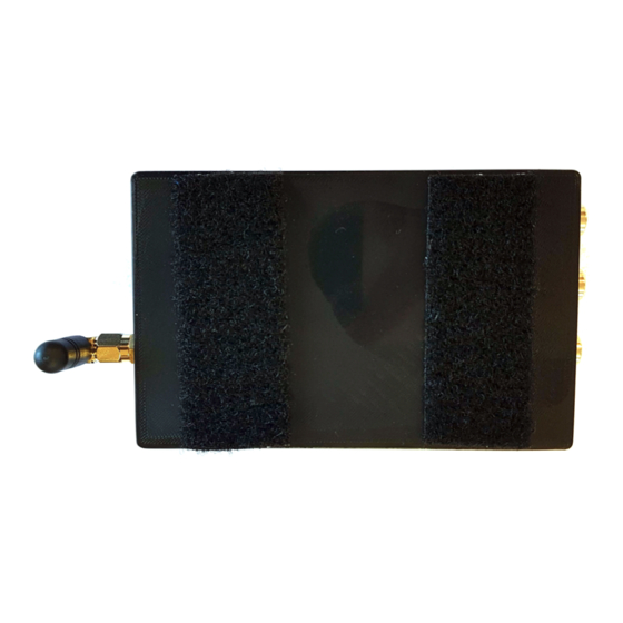
Figure 4•2 — Velcro on the bottom side of the drone Mount the Data Logger onto the drone and connect the cables. Connect the Data Logger to drone’s power outlet using included power cable. Copyright © 2019, SPH Engineering Revision 1 • July 2019... - Page 12 Figure 4•4 — Connecting the Data Logger to the flight controller Any other payload may be connected to Ethernet, I²C, or UART1 connector. The mounted Data Logger with connected cables is shown on the Figure 4•5. Copyright © 2019, SPH Engineering Revision 1 • July 2019...
- Page 13 4 • Installation Data Logger User Manual Figure 4•5 — The Data Logger mounted onto the drone Copyright © 2019, SPH Engineering Revision 1 • July 2019...
-
Page 14: Setup
Connect to Data Logger Using Ethernet Parameters for wired connection are: • IP address: 192.168.0.33 • Port: 22 • Username: root • Password: <empty> Data Logger supports DHCP over Ethrenet, so IP address sets automatically. Copyright © 2019, SPH Engineering Revision 1 • July 2019... -
Page 15: Access To Onboard File System
• Logs directory: /run/media/mmcblk1p1/payload_logs/ Data Logger Configuration In order to configure the Data Logger software one should edit payloadctl.conf file located in /etc/payloadctl/ directory. Table 5•1 — Data Logger parameters Copyright © 2019, SPH Engineering Revision 1 • July 2019... -
Page 16: Setup Interface To Dji A3
DJI GO, choose Me tab, press Login button. Step 2. Enter the credentials mentioned above and press Login. Step 3. Choose Equipment tab, wait for A3 / M600 / M600 Pro, then press Camera button. Copyright © 2019, SPH Engineering Revision 1 • July 2019... - Page 17 Step 4. Connect the DJI A3 flight controller to the PC, run the DJI Assistant 2 and press Login button. Figure 5•3 — DJI Assistant 2 start window Step 5. Enter the credentials mentioned above and press Sign in. Copyright © 2019, SPH Engineering Revision 1 • July 2019...
- Page 18 Step 6. Wait for the main window to appear, then choose SDK tab and check Enable API Control and Ground Station Status checkboxes. Figure 5•5 — Enable API control in DJI Assistant 2 Copyright © 2019, SPH Engineering Revision 1 • July 2019...
- Page 19 Apps tab in developer area. Step 3. Choose ONBOARD SDK and press CREATE APP. Figure 5•6 — DJI Developer area Step 4. Enter correspondent information and press CREATE. Copyright © 2019, SPH Engineering Revision 1 • July 2019...
- Page 20 Important: The DJI A3 may not activate from the first attempt. If there is no connection with flight controller after full system setup, try to repeat step 1 several times with DJI A3 power cycling. Copyright © 2019, SPH Engineering Revision 1 • July 2019...
-
Page 21: General Usage
Figure 6•2 — Good (left) and bad (right) vehicle state in UgCS Client Start the Custom Payload Monitor application and connect to the UCS with your credentials. • Login: admin Copyright © 2019, SPH Engineering Revision 1 • July 2019... -
Page 22: Onboard Software Upgrade
/run/media/mmcblk1p1/ directory), unpack it, and run the install.sh script. For example, when the Data Logger is connected to Linux host via Wi-Fi, run in terminal: scp payloadctl-armhf-*.tar.gz root@10.1.0.1:/run/media/mmcblk1p1/ ssh root@10.1.0.1 cd /run/media/mmcblk1p1 Copyright © 2019, SPH Engineering Revision 1 • July 2019... - Page 23 -2 payloadctl ./install.sh cd .. rm -rf payloadctl-armhf-* reboot There will be ability to enter Data Logger serial number. Four last numerals will be added to Data Logger SSID. Copyright © 2019, SPH Engineering Revision 1 • July 2019...
-
Page 24: Legal Notice
All other trademarks and registered trademarks mentioned in this document are the property of their respective owners. Document License Document contents are licensed under Creative Commons Attribution-NonCommercial-NoDerivatives 4.0 International License (CC BY-NC-ND 4.0). Latest documentation is available on industrial.ugcs.com industrial.ugcs.com ugcs@ugcs.com www.ugcs.com Copyright © 2019, SPH Engineering Revision 1 • July 2019...
Need help?
Do you have a question about the Amass XT30U-F and is the answer not in the manual?
Questions and answers