Table of Contents
Advertisement
Available languages
Available languages
Quick Links
Advertisement
Table of Contents

Summary of Contents for COOLRIDE PB-1
- Page 1 Lenkertaster PB-1 Montage- und Betriebsanleitung English version: see page 7...
- Page 2 Wir beglückwünschen Sie zum Kauf des Lenkertasters PB-1. Lesen Sie diese Montageanleitung aufmerksam durch, bevor Sie den Taster installieren. Die Montage erfordert fortgeschrittene Kenntnisse der KFZ-Elektrik. Bitte neh- men Sie den Anschluss nur dann vor, wenn Sie wissen, was Sie tun. Wir empfehlen die Montage durch eine Fachwerkstatt.
-
Page 3: Technische Daten
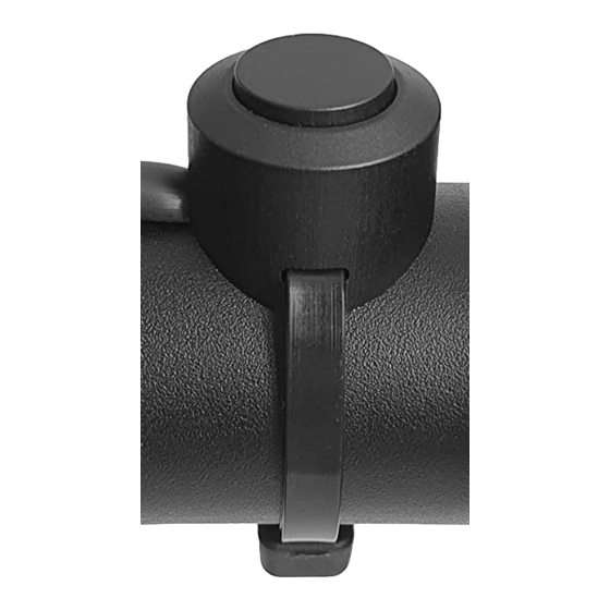
VERWENDUNGSBEREICH Der Lenkertaster PB-1 ist elektrisches Motorradzubehör. Es gibt ihn für metri- sche Lenker mit einem Durchmesser von 22,23 mm sowie für zöllige Lenker mit einem Durchmesser von 25,40 mm. Er weist eine Belastbarkeit von 50mA auf und ist somit geeignet, ein Steuersignal von max. 50mA bereitzustellen. Der Lenkertaster PB-1 ist die ideale Ergänzung zu unserem elektronischen Lastre-... -
Page 4: Montage
LIEFERUMFANG • 1 Lenkertaster PB-1 mit 600 mm langen Anschlussdrähten • 1 Kabelbinder schwarz 3,6 x 150 mm • 1 Schrumpfschlauch schwarz 3,2 x 550 mm MONTAGE Ziehen Sie den Schrumpfschlauch über die Anschlussdrähte. Schrumpfen Sie den Schrumpfschlauch auf der gesamten Länge oder nur am Ende, so dass die farbigen Drähte verdeckt sind und der geschrumpfte Schlauch aus der Öff-... -
Page 5: Garantie
GARANTIE Wir gewähren 5 Jahre Garantie auf dieses Produkt. Schäden, die durch Nicht- beachtung dieser Anleitung entstehen, sind ausgeschlossen. Es gelten die Ga- rantiebedingungen unter www.coolride.de/Garantiebedingungen ENTSORGUNG Sollten Sie dieses Gerät eines Tages entsorgen müssen, be- achten Sie bitte, dass elektronische Geräte nicht mit dem Hausmüll entsorgt werden dürfen. - Page 6 COOLRIDE GmbH Mangenberger Str. 150 42655 Solingen Germany Tel.: +49 212 / 235 70 69 Fax: +49 212 / 68 11 06 94 info@coolride.de www.coolride.de Änderungen, Druckfehler & Irrtum vorbehalten. Abbildungen sind unverbindlich.
- Page 7 Handlebar Switch PB-1 Operation manual...
- Page 8 Congratulations to your new Handlebar Switch PB-1. Please read these instructions carefully before any attempt of installation. The installation requires advan- ced knowledge in vehicle electrics. We recommend ins- tallation by a specialist workshop. If there are any questions unanswered, please contact...
-
Page 9: Field Of Application
1 inch / 25.40 mm. It has a load capacity of 50mA and is the- refore suitable to provide a control signal of max. 50mA. The handlebar switch PB-1 is the ideal complement to our electronic load relay SER-100 but can also be used in combination with other electronic relays or button control units. -
Page 10: Scope Of Supply
SCOPE OF SUPPLY • 1 handlebar switch PB-1 with 600 mm leads • 1 black zip tie 3.6 x 150 mm • 1 black heat shrink tubing 3.2 x 550 mm INSTALLATION Pull the heat shrink tubing over the leads. Shrink the heat shrink tubing along the entire length or only at the end so that the coloured wires are covered and the shrunk tubing can be led out of the notch on the side of the button. -
Page 11: Warranty
We grant a full 5-year warranty on this product. Damage resulting from over- load or disregard of the herein given advise is excluded. Warranty conditions apply as available at www.coolride.de/warranty DISPOSAL Should you need to dispose of this system someday, please note that electronic devices must not be disposed of with household waste. - Page 12 COOLRIDE GmbH Mangenberger Str. 150 42655 Solingen Germany Phone: +49 212 / 235 70 69 Fax: +49 212 / 68 11 06 94 info@coolride.de www.coolride.de Changes, misprints & errors excepted. Illustrations are not binding.
Need help?
Do you have a question about the PB-1 and is the answer not in the manual?
Questions and answers