Table of Contents
Advertisement
Available languages
Available languages
Quick Links
Advertisement
Chapters
Table of Contents

Subscribe to Our Youtube Channel
Related Manuals for Olsen Infinity


Summary of Contents for Olsen Infinity
-
Page 3: Table Of Contents
- Remote Foot Pedal Commands ..........................8 - Working Table ................................8 5.4.1 - Infinity Premium Working Table ........................8 5.4.2 - Infinity Cross Flex Premium Working Table ....................10 - Working Table Arm ............................... 11 - Water Unit ................................12 - Assistant Module .............................. - Page 4 - Monitor Holder (Optional) ............................ 22 - USB Charger ................................. 22 - Cart System (Optional) ............................22 8 - Symbology ..................................23 9 - Olsen Accredited Technical Assistance Network ......................24 10 - Warranty Terms ................................25 11 - Message from the President............................26...
-
Page 5: Introduction
2 - Package Contents The Infinity line equipment is available in 2 packages, one for the chair and the other for the equipment. Check the contents of each package below: Dental Chair Box:... -
Page 6: Water Unit
Note: optional items are defined on the customer's order. - Infinity Models 3.3.1 - Infinity Premium It presents the standard items of the Infinity line (section 3.1). 3.3.2 - Infinity Cross Flex Premium It presents, in addition to the standard items of the Infinity line (section 3.1):... -
Page 7: Parts Identification
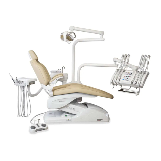
4 - Parts Identification A - Delivery System B - Electrical Panel C - Remote Foot Pedal D - Working Table E - Assistant Module F - Operating Light G - Dental Chair H - Water Unit 5 - Equipment Operating and Description - Before Turning On the Equipment 1º... -
Page 8: Emergency Stop Switch (Optional)
11 - Spittoon Bowl Flush 12 - Metal Handle - Working Table 5.4.1 - Infinity Premium Working Table 1 - Command Panel 2 - Instruments Control Panel The layout of the controls and panels may vary according to customer order and available handpieces. - Page 9 ChronoLub System and Multifunctional Display 1 - Adjustments 2 - Adjust/Enter 3 - Reset/Esc 4 - Multifunctional Display Brushless - Side Panel (Optional) Brushless Electrical Micromotor (Optional) 1 - On/Off Optical Fiber Light 6 - Transmission Indicators Description of controls in section 6.4.4 2 - On/Off Thermo Comfort 7 - Adjustments 3 - On/Off Air Jet...
-
Page 10: Infinity Cross Flex Premium Working Table
5.4.2 - Infinity Cross Flex Premium Working Table 1 - Top Panel Cross 2 - Command Panel 3 - Instruments Control Panel The layout of the controls and panels may vary according to customer order and available handpieces. Some functions indicated on control panel may not be available according to the equipment configuration. -
Page 11: Working Table Arm
Brushless Electrical Micromotor (Optional) Brushless - Side Panel (Optional) 1 - Reverse 2 - Display 3 - Transmission Indicators 4 - Adjustment Keys Description of controls in section 6.3.3 5 - Memory 6 - Selection Instruments Control Panel (3): 1 - Speed Adjustment for Electrical Micromotor 2 - Electrical Micromotor’s Rotation Direction Control 3 - Scaler Intensity Control and Function Selector - Endo/General- Perio... -
Page 12: Water Unit
- Water Unit For water commands: use water commands on remote foot pedal (section 5.3) or command panels on working table (sections 5.4) and assistant module (sections 5.7). The water spouts for spittoon bowl (1) and cup filler (2) are removable. -
Page 13: Zero Position
Seat Up ( ) Seat Down ( ) Backrest Down ( ) Backrest Up ( ) 5.9.1 - Zero Position Press the Zero Position key to automatically adjust the seat to the lowest position and backrest in the highest position simultaneously, to facilitate patient entry and exit. 5.9.2 - Work Position To save a work position: 1º... -
Page 14: Swivel Armrest
5.9.5 - Swivel Armrest To move the swivel armrest: press the trigger (1) and push the armrest down. 6 - Instruments Operation - Pneumatic Handpiece Couplings Before starting the operation connect the handpiece (1) to the coupling by attaching it to the coupling ring (2), ensuring that it is properly connected and that there is no leakage of air or water. -
Page 15: Scaler Adjustments - Operation And Basic Adjustments
gently. Insert the file into the tip of the adapter, thread the tip and then use the Endo wrench (5) to tighten. To remove the adapter, use the Endo wrench (5) to loosen it and then carefully unscrew. 6.3.1 - Scaler Adjustments - Operation and Basic Adjustments To activate the scaler: push the propulsion/activation pedal (6). -
Page 16: Electrical Micromotor (Optional)
- Electrical Micromotor (Optional) Before starting the operation connect the handpiece to the electrical micromotor (2). To activate the rotation: push the propulsion/activation pedal (1). 6.4.1 - Electrical Micromotor Basic Adjustments To adjust the speed: turn the control knob (3) until the desired speed is reached. -
Page 17: Brushless Electrical Micromotor - Side Panel (Optional)
Selected gear ratio: 1:1 Factor: x1.000 Rotation speed: 15 x 1000 = 15,000 rpm To activate memory: press the desired Memory key (6). The display will show the speed and the LED (3) will indicate the present transmission. To record memory: select the transmission and adjust the speed of rotation to store. Press and hold one of the Memory key (7) until the system emits 2 beeps, indicating that the memory has been recorded. -
Page 18: Venturi Saliva Ejector
To adjust input pneumatic pressure: use the adjustment keys (13) to set the parameter. Set maximum input pressure Set minimum activation pressure from 0.20 to 0.40 MPa from 0.03 to 0.10 MPa Note: the micromotor system preset by the factory according to the internal equipment pressure. It is not recommended to change the pressure parameters. -
Page 19: Curing Light (Optional)
- Curing Light (Optional) Before starting the curing light use, install the tip (1) and the light hood (2). To install the tip: first, attach the light hood (2) to the tip (1) and then attach it to the curing light unit (3). -
Page 20: Accessory Operation
7 - Accessory Operation – ChronoLub Control Panel (Optional) 1 - Decreases 2 - Increases 3 - Adjust/Enter 4 - Reset/Esc 7.1.1 - ChronoLub System (Optional) When removing the handpiece from the holder or extending the rod (Cross Flex), the multifunction display will identify whether the coupling is for low or high rotation, show the number of its position on the working table (1 to 5), and a segmented circle that represents the time of use of the handpiece. -
Page 21: Laguage
7.1.4 –Laguage To change the language: press Adjust/Enter (3) for 3 seconds to access the “SETUP” screen. Use the arrows (1 e 2) to select the option 3. LANGUAGE. To select the language: press Adjust/Enter (3) to access “SET LANGUAGE” screen. -
Page 22: X-Ray Viewer
- X-Ray Viewer To turn On the x-ray viewer: press the On/Off key (1) on the command panel. - Anti-Stress System (Optional) To activate/deactivate Anti-Stress system: press the “On/Off” key (5). To enable the automatic massage system: press the “AUT” key (3). The system will start executing 15 types of massage combinations, alternating one combination every minute. -
Page 23: Symbology
8 - Symbology The symbology complies with IEC 60601-1, IEC 60878, ISO 15223-1, ISO 7010. -
Page 24: Olsen Accredited Technical Assistance Network
9 - Olsen Accredited Technical Assistance Network To access the Olsen certified technical assistance network for installation and maintenance, contact us by e-mail export3@olsen.odo.br, or by phone +55 48 2106 6000. The installation and maintenance of the equipment and its accessories must only be carried out by Olsen Technicians. -
Page 25: Warranty Terms
The equipment is stored for more than 6 months after the invoice issuing date; f) For the use of spare parts other than Olsen originals. 6 - The repairing or replacement of parts under the warranty period will not extend its original expiring date. -
Page 26: Message From The President
Our company will always be open to all those who prefer Olsen products, for any necessary information and technical assistance, but especially for comments regarding the relationship with customers. - Page 28 +55 48 2106 6000 export3@olsen.odo.br Registration at Ministry of Health 1028130009 Technician in Charge Eng. Cleber da Costa - CREA SC: S1 116283-5 Cod 5409176 - Rev 04 – 06/04/2021...
- Page 31 - Artículos Opcionales ..............................6 - Modelos ................................... 6 3.3.1 - Infinity Premium ............................6 3.3.2 - Infinity Cross Flex Premium .......................... 6 4 - Identificación de Componentes ............................7 5 - Descripción y Operación del Equipo ..........................7 - Antes de Encender el Equipo ..........................7 - Encendiendo el Equipo ............................
- Page 32 - Cargador USB ............................... 22 - Sistema Cart (Opcional) ............................22 8 - Simbología ..................................23 9 - Red de Servicio Técnico Autorizado Olsen ........................24 10 - Término de Garantía ..............................25 11 - Mensaje del Presidente ............................... 26...
-
Page 33: Introducción
2 - Contenido del Empaque El equipo de la línea Infinity está disponible en 2 empaques, uno para el sillón y el otro para el equipo. Verifique el contenido de cada empaque a continuación: Caja del Sillón:... -
Page 34: Unidad De Agua
Acoples Midwest Nota: artículos opcionales son definidos en el pedido del cliente. - Modelos 3.3.1 - Infinity Premium Presenta los artículos standard de la línea Infinity (sección 3.1). 3.3.2 - Infinity Cross Flex Premium Presenta además de los artículos standard de la línea Infinity (sección 3.1):... -
Page 35: Identificación De Componentes
4 - Identificación de Componentes A - Módulo Odontológico B - Panel Eléctrico C - Pedal D - Mesa Odontológica E - Módulo Asistente F - Lámpara G - Sillón H - Unidad de Agua 5 - Descripción y Operación del Equipo - Antes de Encender el Equipo 1º... -
Page 36: Llave Stop De Emergencia (Opcional)
10 - Comando de Lámpara On/Off 11 - Comando de Agua en la Taza 12 - Manija Metálica - Mesa Odontológica 5.4.1 - Mesa Infinity Premium 1 - Panel de Comandos 2 - Panel de Instrumentos La disposición de los controles y comandos puede variar de acuerdo con el pedido del cliente y piezas de mano disponibles. - Page 37 Sistema ChronoLub y Pantalla Multifunción 1 - Teclas de Ajuste 2 - Adjust/Enter 3 - Reset/Esc 4 - Pantalla Multifunción Brushless – Panel Lateral (Opcional) Micromotor Eléctrico Brushless (Opcional) Descripción de los controles en la 1 - On/Off Luz de la Fibra Óptica 6 - Indicadores de Transmisión sección 6.4.4 2 - On/Off Sistema Thermo Comfort...
-
Page 38: Mesa Infinity Cross Flex
5.4.2 - Mesa Infinity Cross Flex 1 - Panel Superior Cross 2 - Panel de Comandos 3 - Panel de Instrumentos La disposición de los controles y de los comandos puede variar de acuerdo con el pedido del cliente. Algunas funciones indicadas en el panel pueden no estar disponibles debido a la configuración del... -
Page 39: Brazo De La Mesa Odontologica
Brushless – Panel Lateral (Opcional) Micromotor Eléctrico Brushless (Opcional) 1 - Reverse 2 - Pantalla 3 - Indicadores de Transmisión Descripción de los controles en 4 - Teclas de Ajuste la sección 6.3.4 5 - Select 6 - Memory Controles disponibles en el Panel de Instrumentos (3): 1 - Control de Velocidad del Micromotor Eléctrico 2 - Inversor de Rotación del Micromotor Eléctrico 3 - Control de Potencia del Ultrasonido y Selector de Funciones... -
Page 40: Unidad De Agua
- Unidad de Agua Para comandos de agua: utilice los comandos en el pedal (sección 5.3) o paneles de comando (sección 5.4) en la mesa odontológica y en módulo asistente (sección 5.7). Los conductos de agua del llena vasos (1) y de la taza (2) son desmontables. -
Page 41: Posición Cero
Baja Asiento ( ) Sube Asiento ( ) Baja Respaldo ( ) Sube Respaldo ( ) 5.9.1 - Posición Cero Presione el botón Posición Cero para ajustar automáticamente el asiento en la posición más baja y respaldo en la posición más alta simultáneamente, para facilitar la entrada y salida del paciente. -
Page 42: Brazo Abatible
5.9.5 - Brazo Abatible Para mover el brazo abatible: presione el gatillo (1) y empuje el brazo hacia abajo. 6 - Operación de Instrumentos - Acoples Neumáticos para Piezas de Mano Antes de empezar la operación conecte la pieza de mano (1) al acople fijándola con el anillo de acople (2), verificando si está... -
Page 43: Ajustes Del Ultrasonido - Operación Y Ajustes Básicos
6.3.1 - Ajustes del Ultrasonido - Operación y Ajustes Básicos Para activar el ultrasonido: presione el pedal de propulsión/activación (6). Para ajustar la potencia de vibración: gire el botón de control (7) hasta alcanzar la potencia deseada. Para alternar funciones: mantenga el botón de control (7) cerca de la mesa para la función “GP”... -
Page 44: Ajustes Del Micromotor Eléctrico - Pantalla Multifunción
6.4.2 - Ajustes del Micromotor Eléctrico - Pantalla Multifunción Al remover el micromotor eléctrico del soporte o extender la varilla (Cross Flex), la pantalla multifunción (5) identificará el micromotor, el número de su posición en la mesa odontológica (1 al 5), el sentido de rotación y mostrará las barras de velocidad. Para ajustar la velocidad: utilice las teclas para aumentar (7) o disminuir (6) la velocidad. -
Page 45: Micromotor Eléctrico Brushless - Panel Lateral (Opcional)
6.4.4 - Micromotor Eléctrico Brushless - Panel Lateral (Opcional) Antes de iniciar la operación, conecte la pieza de mano al micromotor eléctrico (16). Para activar la rotación: presione el pedal de propulsión/activación (14) o la tecla Manual Star (11). El indicador de On/Off (2) se volverá azul. Para seleccionar el programa: use la tecla Program (8). -
Page 46: Eyector Venturi
- Eyector Venturi Antes de empezar la operación, coloque la cánula en el adaptador de 6,3 o 9,5 mm (3). Para activar la succión: remueva el eyector Venturi (2) del soporte (1). Para desactivar la succión: ponga el eyector (2) en su soporte (1). El adaptador de cánula (3) es desmontable para su limpieza. -
Page 47: Fotocurado (Opcional)
- Fotocurado (Opcional) Antes de iniciar la operación del fotocurado, instale la punta (1) y la visera de protección (2). Para instalar la punta: encaje primero la visera de protección (2) en la punta (1) para después encajar la punta en el fotocurado (3). Empuje la punta en el fotocurado hasta encajarse completamente. -
Page 48: Operación De Accesorios
7 - Operación de Accesorios - Pantalla Multifunción (Opcional) 1 - Decrecimiento 2 - Acrecimiento 3 - Adjust/Enter 4 - Reset/Esc Nota: las opciones de la pantalla “AJUSTE” pueden cambiar si el monitor cardíaco (opcional) está disponible en el equipo (sección 7.1.4). 7.1.1 - Sistema ChronoLub (Opcional) Al remover la pieza de mano del soporte o extender la varilla (Cross Flex), la pantalla multifunción identificará... -
Page 49: Idioma
7.1.4 – Idioma Para cambiar el idioma: presione la tecla Ajustar / Entrar (3) durante 3 segundos para acceder a la pantalla “CONFIGURACIÓN”. Utilice las teclas de ajuste (1 y 2) para seleccionar la opción 3. IDIOMA. Para cambiar el idioma: presione la tecla Ajustar / Entrar (3) para acceder a la pantalla “SELECCIONAR IDIOMA”. -
Page 50: Negatoscopio
que se presione la tecla On/Off (1) o cuando sea regresada la pieza de mano a su soporte. - Negatoscopio Para encender el negatoscopio: presione la tecla On/Off (1) en el panel de comando (sección 5.4 y 5.7). - Sistema Anti-Stress (Opcional) Para activar/desactivar el Anti-Stress: utilice la tecla On/Off (5). -
Page 51: Simbología
8 - Simbología Símbolos en conformidad con las normas IEC 60601-1, IEC 60878, ISO 15223-1, ISO 7010. -
Page 52: Red De Servicio Técnico Autorizado Olsen
9 - Red de Servicio Técnico Autorizado Olsen Para acceder al servicio técnico Olsen para instalación y mantenimiento de su equipo, contáctenos por el correo electrónico export3@olsen.odo.br o por el teléfono +55 48 2106 6000. La instalación y mantenimiento del equipo y sus accesorios se deben realizar solamente por técnicos Olsen. -
Page 53: Término De Garantía
Por adulteraciones en el documento de compra, instalación o servicios; d) Por instalación o asistencia técnica efectuada por persona no autorizada por Olsen; e) Por la no instalación de los productos después de 6 meses, contados de la fecha de compra mencionada en la factura. -
Page 54: Mensaje Del Presidente
Olsen estará siempre a disposición de todos que nos dieron preferencia al adquirir nuestros productos, para toda y cualquier información, auxilio técnico y especialmente comentarios pertinentes a la relación, que esperamos, traiga siempre satisfacción,... - Page 56 +55 48 2106 6000 export3@olsen.odo.br Registro en el Ministerio de Salud de Brasil 1028130009 Responsable Técnico Ing. Cleber da Costa - CREA SC: S1 116283-5 Cod 5409176 - Rev 04 - 06/04/2021...
Need help?
Do you have a question about the Infinity and is the answer not in the manual?
Questions and answers