
Related Manuals for Lavex 978LAVP20D

Summary of Contents for Lavex 978LAVP20D
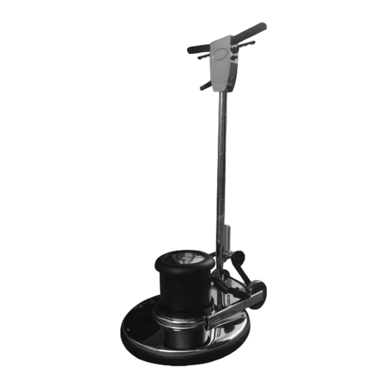
- Page 1 INSTRUCTION MANUAL READ ENTIRE MANUAL BEFORE USE 20" DUAL SPEED ROTARY FLOOR MACHINE #978LAVP20D 08/2020 Lavex Janitorial • 2205 Old Philadelphia Pike • Lancaster, PA 17602...
-
Page 2: General Safety Rules
GENERAL SAFETY RULES WARNING: Read all safety warnings and instructions prior to use. Failure to follow all warnings and instructions may result in electric shock, fire, and/or serious injury. Save all warnings and instructions for future reference. The term “floor machine” in the warnings refers to your corded floor machine. 1. - Page 3 b. Always use appropriate personal protective equipment. Always wear eye protection. Protective equipment such as a dust mask, non-skid safety shoes, hard hat, or hearing protection used for appropriate conditions can reduce personal injuries. c. Ensure the switch is in the off-position before connecting to power source, picking up, or carrying the tool.
-
Page 4: Specific Safety Rules
5. SERVICE a. Have your floor machine serviced by a qualified repair person using only identical replacement parts. This will ensure that the safety of the floor machine is maintained. b. If the replacement of the power cord is necessary, this has to be done by the manufacturer or a designated service organization. -
Page 5: Technical Specifications
TECHNICAL SPECIFICATIONS P17A, P20A, P20D, Type 978LAVP17A 978LAVP20A 978LAVP20D Rated Voltage 110–120V~ Rated Current Frequency 60Hz 50/60Hz Diameter of Accessories 17" 20" 20" Protection Class NOTE: V: Volts A: Amperes Hz: Hertz ~: Alternating Current INSTRUCTION MANUAL • 5... -
Page 6: Installation Instructions
INSTALLATION INSTRUCTIONS 1) Put on the handle 2) Remove the wrench and install the axle 3) Put the wrench through the 4) Link motor to handle support iron and install it again 5) Install the water tank 6) The water pipe connects the accessories and install the water water tank outlet and the base tank on the handle... -
Page 7: Operation And Maintenance
OPERATION AND MAINTENANCE WARNING: Be sure to read and understand this manual in its entirety before operation. Failure to do so may result in damage or injury. PROPER SETUP AND PREPARATION Ensure that all components are assembled tightly and secured, and that power source matches voltage of your unit. -
Page 8: Safety Information
SAFETY INFORMATION Failure to follow the instructions below could lead to damage or personal injury 1. This unit is for commercial janitorial use only, you must be trained before operating unit. 2. Do not operate unit unless it is completely assembled, and you have ensured that every component is secured tightly. -
Page 9: Component Structure
COMPONENT STRUCTURE 1. Switch Handle 2. Safety Switch 3. Power Cord 4. Aluminum Alloy Handle 5. Water Tank Drain Valve 6. Water Tank (Optional) 7. Cord Wrap 8. Handle Adjumentment Knob 9. Chassis Colloidal Particles 10. Motor Cover 11. Capacitor and Cover 12. -
Page 10: Explosion Diagram
EXPLOSION DIAGRAM 1. Handle 2. Handle Cover 3. Switch Handle 4. Switch 5. Power Cord 6. Hand Wheel 7. Pad 8. Aluminum Column 9. Wrench 10. Buttress Iron 11. Wheel Axle 12. M6*15 Outer Hexagon Bolt 13. Back Wheel 14. Wheel Axle 15.
Need help?
Do you have a question about the 978LAVP20D and is the answer not in the manual?
Questions and answers