Advertisement
Quick Links
Network Interface Module
SYSTXBBNIM01
NOTE: Read the entire instruction manual before starting the
installation.
This symbol → indicates a change since the last issue.
TABLE OF CONTENTS
SAFETY CONSIDERATIONS .....................................................1
INTRODUCTION ..........................................................................1
INSTALLATION ...........................................................................1
Check Equipment and Job Site...........................................1
Component Location and Wiring Considerations ..............1
Install Components ..............................................................2
Ventilator (HRV/ERV) Wiring ...........................................2
Dual Fuel with 1-Speed Heat Pump Wiring ......................2
Var.-Spd. Indoor Units with 2-Spd. Outdoor Unit Wiring.2
SYSTEM START-UP ....................................................................2
LED INDICATORS.......................................................................2
FUSE ..............................................................................................2
24 VAC POWER SOURCE ..........................................................2
SAFETY CONSIDERATIONS
Read and follow manufacturer instructions carefully. Follow all
local electrical codes during installation. All wiring must conform
to local and national electrical codes. Improper wiring or installa-
tion may damage Evolution Control System. Recognize safety
information. This is the safety-alert symbol
symbol on the equipment and in the instruction manual, be alert to
the potential for personal injury. Understand the signal words
DANGER, WARNING, and CAUTION. These words are used
with the safety-alert symbol. DANGER identifies the most serious
hazards, which will result in severe personal injury or death.
WARNING signifies a hazard, which could result in personal
injury or death. CAUTION is used to identify unsafe practices,
which would result in minor personal injury or product and
property damage. NOTE is used to highlight suggestions which
will result in enhanced installation, reliability, or operation.
Installation and Start-Up Instructions
EVOLUTION NETWORK INTERFACE MODULE
SYSTXBBNIM01
A03231
. When you see this
—1—
Cancels: NEW
INTRODUCTION
The Network Interface Module (NIM) is used to interface the
following devices to the Evolution ABCD bus so they can be
controlled by the Evolution System. The following devices do not
have communication ability and the NIM is required to control:
• A Heat Recovery Ventilator / Energy Recovery Ventilator
(HRV/ERV) (when zoning is not applied).
• A non-communicating single-speed heat pump with a variable-
speed furnace (dual fuel application only).
• A non-communicating two-speed outdoor unit (R-22 Series-A
unit).
INSTALLATION
I. CHECK EQUIPMENT AND JOB SITE
INSPECT EQUIPMENT — File claim with shipping company,
prior to installation, if shipment is damaged or incomplete.
II. COMPONENT LOCATION AND WIRING CONSIDER-
ATIONS
WARNING: ELECTRICAL SHOCK HAZARD
Failure to follow this warning could result in personal
injury or possible equipment damage.
Disconnect power before beginning installation.
NOTE: All wiring must comply with national, local, and state
codes.
LOCATING NETWORK INTERFACE MODULE (NIM)
— Select a location near the variable-speed furnace or fan coil
where wiring from equipment can come together easily.
NOTE: Do not mount NIM in outdoor unit. The NIM is
approved for indoor use only and should never be installed with
any of its components exposed to the elements.
The NIM may be installed in any area where temperature remains
between 32° and 158° F, and there is no condensation. Remember
that wiring access is likely the most important consideration.
CAUTION: ELECTRICAL OPERATION HAZARD
Failure to follow this caution will result in equipment
damage or improper operation.
To prevent possible damage to NIM, do not mount on
plenum, duct work, or flush against furnace.
WIRING CONSIDERATIONS — Ordinary thermostat wire is
ideal when wiring the Evolution System (shielded cable is not
necessary). Use 18 - 22 AWG or larger for typical installations.
Lengths over 100 ft. should use 18 AWG or larger wire. Cut off or
fold back and tape any unneeded conductors. Plan the routing of
wiring early to avoid possible problems later.
NOTE: ABCD bus wiring only requires a four-wire connection;
however, it is good practice to run thermostat cable having more
than four wires in the event of a damaged or broken wire during
installation.
II NIM01-0-1
02-04
Advertisement

Related Manuals for Bryant SYSTXBBNIM01

Summary of Contents for Bryant SYSTXBBNIM01
- Page 1 Installation and Start-Up Instructions EVOLUTION NETWORK INTERFACE MODULE SYSTXBBNIM01 Network Interface Module SYSTXBBNIM01 NOTE: Read the entire instruction manual before starting the installation. This symbol → indicates a change since the last issue. TABLE OF CONTENTS SAFETY CONSIDERATIONS ...1 INTRODUCTION ...1 INSTALLATION ...1...
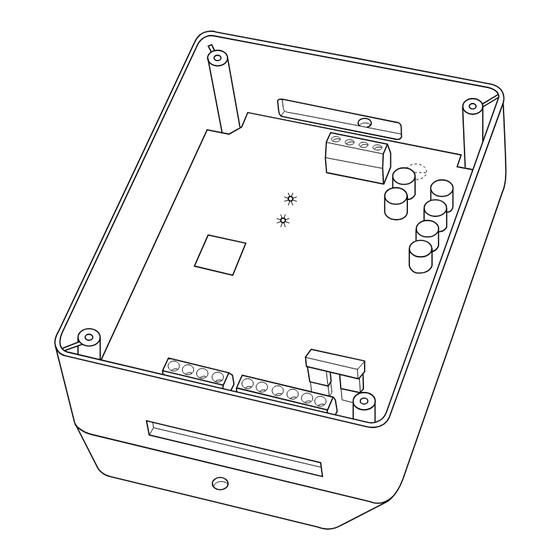
- Page 2 1. Remove top cover and mount NIM to wall using screws and wall anchors provided. IV. VENTILATOR (HRV/ERV) WIRING HRV / ERV INSTALLATION — The NIM can control a Bryant Heat Recovery Ventilator / Energy Recovery Ventilator (HRV / ERV). Connect four wires from ventilator control board (see ventilator installation instructions for details) to connector labeled (YRGB).
- Page 3 Ventilator Connection Fig. 2 — Ventilator (HRV / ERV) Connection Ventilator (if used) 1 Spd. Heat Pump Fig. 3 — Variable-Speed Furnace with 1-Spd. Heat Pump (Dual Fuel) Ventilator (if used) Outdoor 2-Spd. AC or HP (R-22 Series-A unit) Fig. 4 — 2-Spd Non-Communicating AC or HP (R-22 Series-A Unit) with Variable-Speed Indoor Unit Green Yellow...
- Page 4 FUSE 3-AMP SEC-2 SEC-1 FAC-2 © 2004 Bryant Heating & Cooling Systems 7310 W. Morris St. Indianapolis, IN 46231 ACRDJ 1-AMPS 115VAC EAC-1 VS HSI HI LO Fig. 5 — HK42FZ022 Furnace Board with Outdoor Air Temperature Connection —4— Sensor A03230 Printed in U.S.A.
Need help?
Do you have a question about the SYSTXBBNIM01 and is the answer not in the manual?
Questions and answers