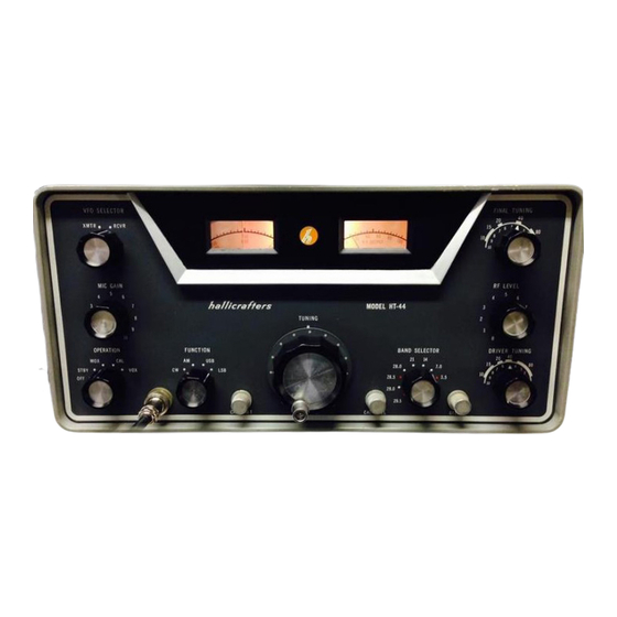
Hallicrafters HT-44 Operation And Maintenance Manual
Hide thumbs
Also See for HT-44:
- Operating and service instructions (33 pages) ,
- Operating and service instructions (40 pages)

Related Manuals for Hallicrafters HT-44


Summary of Contents for Hallicrafters HT-44
- Page 1 SUPPLEMENT OPERATION AND MAINTENANCE MANUAL HALLICRAFTERS HT-44 WDØGOF 02/28/2019...
-
Page 2: Introduction
Walter A. Cates, WDØGOF. Unless specifically credited to a contributor all processes, ideas, drawings, data sheets and opinions contained here are those of the author. Special thanks to Bernie, WDØGMD for the loan of his HT-44 for test and research for writing this document. -
Page 3: Table Of Contents
SUPPLEMENT TO OPERATION AND MAINTENANCE MANUAL HT-44 Contents INTRODUCTION ..................................2 1, REPAIR AND REFURBISHING..............................6 1-1, RECAPPING ................................... 6 1-2, AFTERMARKET MODIFICATIONS ..........................6 1-3 TEST EQUIPMENT REQUIRED ............................6 1-4, INITIAL POWER UP ............................... 7 1-4-1, VOLTAGE VARIFICATION TESTS ..........................8 1-4-2, INITIAL BIAS ADJUSTMENT ........................... - Page 4 1-8-5, 40 METER ADJUSTMENT ............................. 14 1-8-6, 80 METER ADJUSTMENT ............................. 14 1-9, PA NEUTRALIZATION ..............................14 1-9-1, NEUTRALIZATION PRE-TUNE ..........................15 1-9-2, NEUT. SET UP ..............................15 1-10, CARRIER DRIVE LEVEL .............................. 15 1-10-1 CARRIER LEVEL ADJUSTMENT ..........................15 1-11, MODULATION AND CARRIER SUPPRESSION ......................
- Page 5 3-3-3,.CARRIER OSC ............................... 29 MODE / VOLTAGE CHART............................29 3-3-4 HET OSC ................................29 HET OSC VOLTAGE CHART ............................. 29 3-3-5 VF0 ..................................29 VFO VOLTAGE CHART ............................29 3-3-6, MIXER-IF ................................29 MIXER/IF VOLTAGE CHART ........................... 29 3-4 MISC .................................... 30 3-4-1, ANALYZER/SCOPE PICKUP ..........................
-
Page 6: 1, Repair And Refurbishing
• Driver tube capacitive pick-up (see 2-2-4) As a general rule I have tried to eliminate specialized or expensive test equipment. Systems like the HT-44 cause me to make acceptation. The phasing adjustments of the balanced modulators as described in the manual can be quite tedious. -
Page 7: Initial Power Up
It will remain there throughout all testing. It will need 2.5v full scale and 5 or 10v full scale switch positions. Remove the top and bottom covers of the HT-44. Remove the case. BE AWARE, from this moment on you are exposed to LETHAL HIGH VOLTAGE. -
Page 8: 1-4-1, Voltage Varification Tests
1-4-1, VOLTAGE VARIFICATION TESTS We are now going to measure the B+ 250vdc, the regulated 150vdc, the High Voltage 575vdc and measure and preset the bias voltage. This will be a no-load condition and the voltages will read 5 to 10% high. Insure all the cable connections are correct. -
Page 9: 1-5-1-1, Carrier Oscillator Fault Analysis
1-5-1-1, CARRIER OSCILLATOR FAULT ANALYSIS If the equipment failed the tests in 1-5-1 the following measurements should aid in fault analysis. Setup in “safe mode”. You will be making measurements at the junction of R1 and R2, the bottom of R2, and V1 pin1, pin2 and pin3. To get accurate measurements you must insure that your meter does not load the oscillator. -
Page 10: Vfo Test And Alignment
1-5-3-1 VFO TEST AND ALIGNMENT SETUP: Connect frequency counter to the switch side of C17 using a 10x scope probe. Preset C29 to the center of its tuning range. Adjust the CAL RESET to center of its rotation. Turn the OPERATION switch to MOX. Turn the FUNCTION switch to AM mode. -
Page 11: Driver/Pa Pretest & Setup
1-6, DRIVER/PA PRETEST & SETUP In order to properly test and analyze the audio, phasing and I.F. circuits properly the driver and PA need to be at or near normal. The 6DQ5 final tubes must be a matched pair. If you are unsure of the conditions of the final tubes proceed to section 3-1, ERRATA SHEET TUBE MATCHING and follow the instructions. -
Page 12: First Mixer, 6-6.5Mhz I.f., Second Mixer
1-7 FIRST MIXER, 6-6.5MHz I.F., SECOND MIXER The first mixer, 6meg IF and second mixer train is composed of V6, T3, V7A, T4 and V8. 1-7-1, MIXER/I.F. SETUP & ALIGNMENT Power up in safe mode. Allow 10 minute warm up. Locate test points TP 1, TP 2 and TP3. -
Page 13: Driver / Pa Alignment
1-8 DRIVER / PA ALIGNMENT The driver/pa alignment can be done in either CW mode with telegraph key plugged in or AM mode with mic attached and with the MIC GAIN set to zero. CW is preferred. Throughout the driver / pa alignment you will need to constantly adjust the RF LEVEL to stay at 100 watts. Keep backing down on the RF LEVEL to insure you are seeing the true coil peaks. -
Page 14: 1-8-2, 10 Meter Adjustment
1-8-2, 10 METER ADJUSTMENT Set the band switch to 28.5 tune the VFO to 750. Set the DRIVER TUNING per the photo above. Preset the FINAL TUNING in the same manner as you did the DRIVER TUNING. Key the transmitter and advance the RF LEVEL until you start to see a rise in plate current (on the meter attached to power supply monitor jacks). -
Page 15: 1-9-1, Neutralization Pre-Tune
1-9-1, NEUTRALIZATION PRE-TUNE Power up in the safe mode. Set the band switch to 21. Set the VFO dial to 360. Set the RF LEVEL to 8. Switch to CW and adjust the DRIVER TUNE and FINAL TUNE for max power out. Reduce the RF LEVEL as needed to keep the power out at 45 - 65 watts. -
Page 16: Modulation And Carrier Suppression
1-11, MODULATION AND CARRIER SUPPRESSION If you do not have a spectrum analyzer perform the tests and adjustments described in the factory manual. These will be found in section 9-11, paragraphs 1 through 23. If at all possible, buy, beg or borrow a spectrum analyzer. One day about 40 years ago while working on a Collins ARC/38A, I wanted to look at the spectrum on SSB and also monitor the mod envelope in AM. -
Page 17: Carrier Suppression Test And Adjustment
1-11-1 CARRIER SUPPRESSION TEST AND ADJUSTMENT Set up the 44 in the safe mode, power up and allow 15 minutes for warm up. The warm up is important, you must insure all components are up to operating temperature. Tune for max power in the center of any band in CW or AM. •... -
Page 18: Unwanted Sideband Rejection
1-11-2 UNWANTED SIDEBAND REJECTION Set up the 44 in the safe mode, power up and allow 15 minutes for warm up. The warm up is important, you must insure all components are up to operating temperature. Tune for max power in the center of any band in CW or AM. 1. -
Page 19: Subsystem Adjustment & Trouble Shooting
2 SUBSYSTEM ADJUSTMENT & TROUBLE SHOOTING 2-1 MICROPHONE AUDIO 2-1-1, VOLTAGE CHART NOTE: On the unit under test the +250-volt buss actually measured 315vdc. It is not uncommon for the 250vdc buss to run from 300 to 330vdc with AC line voltages between 120 and 124vac. 57v/(50v STBY) 5 260v/(227 AM KEYED) 1 260V/(227 AM KEYED) -
Page 20: Vox Test And Troubleshooting
2-2, VOX TEST AND TROUBLESHOOTING Relay K1 provides the internal switching for the transmitter. Tube V13B is the control element for K1. V13B gets its turn on command from the PTT line the VOX subsystem. When in the VOX mode a sample of the first mic amp (V2) output is fed to the VOX circuit (V12A and V13A). -
Page 21: 2-2-1, Vox Test Setup
3, Control in the upper third of rotation indicates component drift or weak tube in the VOX train. • Leave all controls on the HT-44 as they are for the next series of tests. If the VOX fails to operate properly there is a fault in the vox train. Insure the controls are set per 2-2-1 and proceed to 2-2-2-1. -
Page 22: 2-2-3, Anti-Trip
2-2-3, ANTI-TRIP The anti-trip circuits are a sub-system of the VOX system. The purpose is to keep the receiver audio generated by the speaker from triggering the transmitter. A sample of the receiver audio is fed to the anti-trip circuit, processed and presented as a negative dc voltage proportional to the amplitude of the audio sample. -
Page 23: Driver/Pa Troubleshooting
2-2-4 DRIVER/PA TROUBLESHOOTING You will need a tube capacitive pickup adaptor for tests in this section. It can be constructed from an old tube shield with the base cut off so that it does not contact chassis ground. Pick a size that fits snuggly over the 12BY7. 2-2-4-1 STATIC DC VOLTAGES Set up in the safe mode, allow 10 minutes warm up. -
Page 24: Aalc
2-2-5 AALC When a small amount of grid current occurs in the final amplifier, an audio signal appears on the bias line in proportion to the amount of grid current. This audio component is coupled to the AALC circuits for processing. The resulting DC voltage is fed as a gain control to V7, the 6Meg I.F. -
Page 25: 2-2-7, Going On The Air With The 44
Return to the safe mode. 2-2-7-2, PA OUTPUT FINAL ADJUSTMENT As stated before, the HT-44 is capable of much more than 130 watts output. However, the audio circuits were not designed to drive the system at higher power levels. Set up and turn on the 44 in the safe mode. Allow at least 15 minutes for everything to come up to temperature. -
Page 26: 3, Attachments
3, ATTACHMENTS 3-1, ERRATA SHEET TUBE MATCHING... -
Page 27: Internal R/T Relay Mod
3-2, INTERNAL R/T RELAY MOD... -
Page 28: Data Sheets
3-3, DATA SHEETS 3-3-1 MIC AUDIO DATA VOLTAGE CHART 57v/ (50v STBY) 260v/ (227 AM KEYED) 260v/ (227 AM KEYED) 0.34V 2.6V/ (3.0V STBY) 60v/ (160 STBY) //////////////////////////////////////////// 6 260v/ (227 AM KEYED) //////////////////////////////////////////// -0.7V / (140V cw) //////////////////////////////////////////// 7 0.0 ///////////////////////////////////////////// /////////////////////////////////////////// ////////////////////////////////////////////... -
Page 29: 3-3-2, Vox Signal & Voltage Measurments
3-3-2, VOX SIGNAL & VOLTAGE MEASURMENTS If at any time during this procedure the transmit power comes up to full remember to keep the transmit cycle short. With the equipment set as per section 2-2-1 we will switch to VOX and set the VOX control to the center of its rotation MEASURED WITH SCOPE MEASURED WITH DVM TIE POINT OF R80 &... - Page 30 317/277 1.1/0.9 158/57 61/53 * 317/274 Voltages with * will differ dependent upon band selection. Measured in MOX, AM. First voltage unkeyed/second voltage keyed. 3-4 MISC 3-4-1, ANALYZER/SCOPE PICKUP...
Need help?
Do you have a question about the HT-44 and is the answer not in the manual?
Questions and answers