Table of Contents
Advertisement
Quick Links
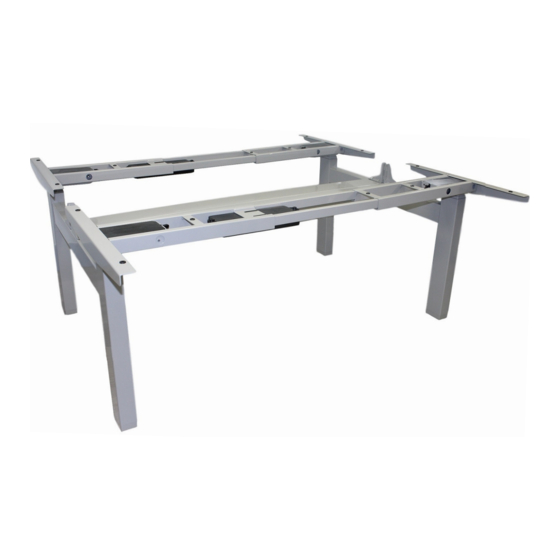
FLT-08
TABLE LIFT SET - 4 LEGS - 3 STEP - STROKE SIZE 25.5"
The FLT-08 is a four column table lift set with a 25.5" stroke size and 220 lbs of lifting force per
set. It is designed for two separate table tops with complete individual control using the two
remotes provided. Each remote has full programmable preset functions for control over the
quiet and fast table lift sets. This model comes with all appropriate cables, control boxes,
remotes, and hardware for installation. Table tops are not included.
*Please note that all 4 legs will not sync together as each pair is controlled individually with its
own remote. The FLT-08 comes with an optional attachment to make it an eight leg lifting set
for large office/ home spaces. If you would like to purchase this attachment please contact us at
1-800-676-6123.
HOW TO ORDER
1.800.676.6123
|
sales@progressiveautomations.com
|
www.progressiveautomations.com
Page 1 of 7
Advertisement
Table of Contents

Subscribe to Our Youtube Channel
Summary of Contents for Progressive FLT-08
- Page 1 TABLE LIFT SET - 4 LEGS - 3 STEP - STROKE SIZE 25.5" The FLT-08 is a four column table lift set with a 25.5" stroke size and 220 lbs of lifting force per set. It is designed for two separate table tops with complete individual control using the two remotes provided.
- Page 2 CAUTION/INFORMATION USE/LIABILITY Page 2 of 7 HOW TO ORDER 1.800.676.6123 sales@progressiveautomations.com www.progressiveautomations.com...
- Page 3 PARTS Page 3 of 7 HOW TO ORDER 1.800.676.6123 sales@progressiveautomations.com www.progressiveautomations.com...
- Page 4 ASSEMBLY INSTRUCTIONS STEP 1 STEP 3 Prepare the four legs (Parts 5 & 6) as shown in the Use 16 of the M6x10 Machine Screws to attach the Frames to picture below. the Legs. Put the Center Rails into the Frames as shown in the picture below.
- Page 5 ASSEMBLY INSTRUCTIONS STEP 5 (optional) STEP 7 Insert four of the M6x10 Machine Screws into the holes Use 24 of the M6x10 Machine Screws to attach the of the Beams then assemble the Cable Tray as shown Center Rails to the Frames and the Screen Holder. in the picture below.
-
Page 6: Dimensional Drawing
DIMENSIONAL DRAWING 25.5" 23.5" 55.3" with Cable Tray 34.4" HOW TO ORDER 1.800.676.6123 sales@progressiveautomations.com www.progressiveautomations.com... -
Page 7: Operational Procedure
OPERATIONAL PROCEDURE Once your table lift is installed it is simple to operate. Just use the wired remotes for full up/down motion control. Use the up button to raise the table lift and use the down button to lower it. You can preset up to 4 positions by following this simple procedure: Use the up/down buttons on the remote to find your desired height(s), then press “M”... -
Page 8: Troubleshooting
TROUBLESHOOTING If your desk is not functioning it might need to be reset. Follow the RESET procedure from page 6. If your hand remote has an LED display and it displays "RST" (reset), perform the reset procedure from page 6. If the LED displays shows an error message ("Er1"... - Page 9 SETTING UPPER & LOWER LIMITS Upper Limit To set the upper limit, use the UP/DOWN buttons to move the table lift to your desired max height position. Once it is at the desired position, press and hold the "M" until the LED display flashes "S-"...
- Page 10 MODIFIYING LED DISPLAY Press the DOWN button on the Hand Remote until the base reaches its lowest position. Measure the height of the base from the floor and if the number on the LED display does not match your measurements, follow the steps below: Press and hold the DOWN button again until the LED display reads "RST".
Need help?
Do you have a question about the FLT-08 and is the answer not in the manual?
Questions and answers