Advertisement
Quick Links
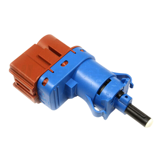
INSTRUCTIONS / INSTRUCCIONES / FAE 24796 / 24849 / 24853
ASSEMBLY INSTRUCTIONS
GB
FAE 24796 / 24849 / 24853
(These references FAE are not replaceable between each other)
A - Unplug the connector (1) from the Stop Light
Switch (2).
To remove the Stop Light Switch, it has to be rotated
clockwise (approx. 45º).
B - Take the new Stop Light Switch FAE part number
24796 / 24849 / 24853.
CAUTION: This type of Switch contains an internal
mechanism, which can be damaged if it is not
installed and adjusted correctly. The Switch can be
tested electrically exclusively when it is totally
assembled.
The position of the switch when supplied is the
"deactivated Switch ".
C - Maintain the foot brake pedal in its rest position.
IMPORTANT: Support the pedal in its rest position
while the installation of the Switch is being done.
Insert the Switch (2) inside the hole of the pedal body
(it has only one possible position) pressing the lifter
against the pedal to fit its position.
To fix the Switch into its position, tthe Switch has to
be rotated counter clockwise (approx. 45 º) obtaining
the final assembly position.
The switch position when assembled is the
"activated Switch " position and can now be tested
electrically and checked.
D - IMPORTANT: Ensure that the switch is turned to
the correct position. This action locks the plunger
adjustment. The break light switch is correctly
installed if the internal stop pin (white arrow) of the
brake light switch is fully seated at end of slot in
outer shell (black arrow).
• Reconnect brake light switch connector and verify
the connection.
• Operate brake pedal to verify proper function and
brake light activation.
• Reinstall covers and trim panels.
Remember to erase brake light switch related faulty
messages after installing the new switch.
video
instructions
INSTRUCCIONES DE MONTAJE
ES
FAE 24796 / 24849 / 24853
(Estas referencias FAE no son intercambiables entre sí)
A - Desenchufar el conector (1) del Interruptor de Stop
(2).
Para retirar el Interruptor de Stop se ha de girar en
sentido horario (aprox. 45°).
B - Obtener el nuevo Interruptor de Stop referencia
FAE 24796 / 24849 / 24853.
PRECAUCIÓN: Este tipo de Interruptor contiene un
mecanismo interno, el cual puede ser dañado sino se
instala y ajusta correctamente. El Interruptor solo
puede ser testeado eléctricamente cuando está
montado. La posición del interruptor cuando se
suministra es la de "Interruptor desactivado"
C - Mantener el pedal de freno en su posición de
reposo.
IMPORTANTE: Sostener el pedal en su posición de
reposo mientras se hace la instalación del Interruptor.
Insertar el Interruptor (2) dentro del orificio del cuerpo
del pedal (solo tiene una posición posible) presionando
el empujador contra el pedal para ajustar su posición.
Para fijar el Interruptor a su posición, se ha de girar el
Interruptor en sentido antihorario (aprox. 45°)
consiguiendo la posición de montaje definitiva. La
posición del interruptor cuando está montado es la de
"Interruptor activado". En esta posición es cuando se
puede comprobar su funcionamiento.
D - IMPORTANTE: Debe asegurarse que el Interruptor
se gire hasta la posición correcta. Esta acción cierra el
ajuste del émbolo. El interruptor esta bien montado,
cuando el borne interno (flecha blanca) del interruptor
de freno está bien situado al final de la ranura del
armazón externo (flecha negra).
• Enborne de nuevo el conector del interruptor de
freno y verifique su buena fijación.
• Accione el pedal de freno para verificar su buen
funcionamiento y la activación de las luces de freno.
• Reinstale las cubiertas y las pantallas.
Tras la instalación del nuevo interruptor, no olvide
borrar los códigos de mensajes de error relativos al
interruptor de freno.
www.fae.es
interactive catalog
responsive web design
A
B
C
D
www.fae.es
2
1
2
968084
Advertisement

Related Manuals for FAE 24796


Summary of Contents for FAE 24796
- Page 1 INSTRUCTIONS / INSTRUCCIONES / FAE 24796 / 24849 / 24853 ASSEMBLY INSTRUCTIONS INSTRUCCIONES DE MONTAJE FAE 24796 / 24849 / 24853 FAE 24796 / 24849 / 24853 (These references FAE are not replaceable between each other) (Estas referencias FAE no son intercambiables entre sí)
- Page 2 Pour retirer le Contacteur de Feu Stop il faut le muss dieser ca. 45º nach rechts gedreht werden. tourner de 45º dans le sens horaire. B - Je nach Bedarf, einen neuen Stopschalter FAE 24796 / B - Prenez le nouveau Contacteur de Feu Stop 24849 / 24853 bereithalten.
Need help?
Do you have a question about the 24796 and is the answer not in the manual?
Questions and answers