
Summary of Contents for DLC SA-230FA
- Page 1 SA-230FA / SA-260FA Instruction Manual Please read manual carefully before using and keep it well.
-
Page 2: Table Of Contents
Contents Important Safety Instructions ..................2 Explanation of Safety Symbols and Notes ..............4 Unpacking ........................6 Installation ........................7 4.1 Environment ......................7 4.2 Install the sterilizer ....................7 Introduction ......................... 12 5.1 Intended Use ......................12 5.2 Description of the Sterilizer ...................12 5.2.1 External View ....................12 5.2.2 Internal Configuration .................13 5.2.3 Control Panel (Re-Dry Program) ..............14... -
Page 3: Important Safety Instructions
1. Important Safety Instructions Caution: Please install, operate and maintain the sterilizer in accordance with this Instruction Manual. Failure to do so could result in serious injury or damage to the unit. Warning: The outer casing and metal surfaces of the sterilizer will be hot during operation, please do not touch it. - Page 4 user is required. Warning: If the ALARM indicator light illuminates, the machine is over-pressure or overheated. The sterilizer will shut down automatically. Contact your supplier for service support. Warning: Failure to follow the Maintenance Instructions will adversely affect performance and lifespan of the sterilizer, and may invalidate the warranty. Warning: Always keep the sterilizer clean.
-
Page 5: Explanation Of Safety Symbols And Notes
2. Explanation of Safety Symbols and Notes Caution, consult instruction manual for use Protective earth (ground) Alternating Current Attention! Hot surface Disposal of Electrical & Electronic Equipment (WEEE): This product should be handed over to an applicable collection point for the recycling of electrical and electronic equipment. - Page 6 damage to or destruction of the equipment or other property.
-
Page 7: Unpacking
3. Unpacking Caution: It will require at least two (2) or more people to carry the sterilizer to avoid dropping it off by mistake. Wall Base Figure 1 – Packaging Cut the banding Lift off the top cover of the carton Remove the wall and the foam packaging inserts Carefully lift the sterilizer from the packaging base Check all accessories are present as follows (accessories are packed inside the sterilizer... -
Page 8: Installation
4. Installation 4.1 Environment This equipment has been designed for use in accordance with the International EMC (Electromagnetic Compatibility) Standards. In view of different environments, please follow the instructions given below to eliminate interference, if necessary. Move the equipment or rotate its direction; Enlarge the space between the equipment and other machines;... - Page 9 Open the water reservoir cap; pour distilled water into the water reservoir as Figure 2. Water Reservoir Cap Water Level Figure 2 Caution: Please fill Distilled Water Only into the unit. Take care not to overfill the yellow water level mark as Figure 3 and Figure 8. Yellow Water level Mark Water Level Figure 3...
- Page 10 Install the heater cover to the chamber as Figure 4. (standard accessory) Ensure the rounded edge is towards the back and the vertical front edge of the cover locates securely into the corresponding slots in the lower part of the chamber opening. Heater Cover Chamber Water Stopper...
- Page 11 D. Install the tray frame as Figure 6. (optional accessory) Caution: The frame should be installed as Figure 6 below. The indention of the frame will pass the bushing in the chamber. Tray Frame Indention Figure 6 – Tray Frame Install the tray as Figure 7.
- Page 12 G. Ensure the Power Switch is in OFF “O” position, and then plug the power cord into a separate (dedicated) mains socket. Warning: A separate (dedicated) socket is required for the sterilizer. Make sure the socket is earthed and can offer the capacity of 16 A / 230V AC. Warning: The plug is one of the measures of emergency cutoff;...
-
Page 13: Introduction
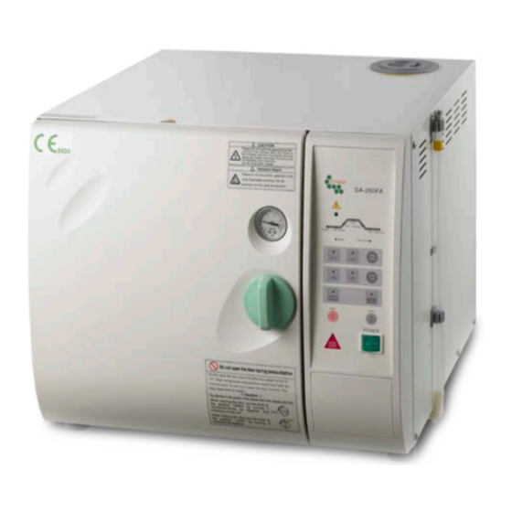
5. Introduction 5.1 Intended Use This product is a tabletop high pressure steam sterilizer which is designed and developed for the sterilization of wrapped and unwrapped items. It can also perform sterilization of liquid which is not for medical purpose*. (*Liquid program is optional by order.) 5.2 Description of the Sterilizer Water Reservoir Cap... -
Page 14: Internal Configuration
Maintenance Cover Exhaust Hose / Water Level Indicator Power Cord Figure 10 – Bottom View 5.2.2 Internal Configuration Water Level Sensor (Under heater cover) Heater Water Stopper Figure 11 – Inside of Chamber... -
Page 15: Control Panel (Re-Dry Program)
5.2.3 Control Panel (Re-Dry Program) Process Status Indicator Individual LED light to Visual Alarm Indicator Light indicate the current status of Indicates over-temperature or the sterilization program. over-pressure in the chamber Power Add Water Heating Low Water Indicator Light ... -
Page 16: Control Panel (Liquid Program*) *Optional By Order Request
5.2.4 Control Panel (Liquid Program*) *Optional by order request. Process Status Indicator Individual LED light to Visual Alarm Indicator Light indicate the current status of Indicates over-temperature or the sterilization program. over-pressure in the chamber Power Add Water ... -
Page 17: Operation
6. Operation 6.1 Operation Overview 6.1.1 Operation Overview (Re-Dry Program) Put the sterilization items and close door Normal Re-Dry Sterilization Select Sterilization Temperature Select Re-Dry Button Select Sterilization Time Select Dry/No Dry Press “START” Button Add Water and Heat Re-Dry Program Starts Heat to Selected Sterilization Temperature ●... -
Page 18: Operation Overview (Liquid Program) *Optional
6.1.2 Operation Overview (Liquid Program) *Optional Put the sterilization items and close door Liquid Program Normal Sterilization Select Sterilization Temperature Select Liquid Program Select Sterilization Time Select Dry/No Dry Press “START” Button Add Water and Heat Heat to Selected Sterilization Temperature ● Sterilization Starts Normal Sterilization Liquid Program... -
Page 19: Normal Sterilization Program
6.2 Normal Sterilization Program Follow “4. Installation” on Page 7 to finish installation first. Follow “4.2 Install the sterilizer” on Page 7 to make sure the water inside reservoir is sufficient. C. Check the Pressure Gauge is reading ZERO, and then open the door by turning the door knob 90°... - Page 20 G.2 Press “STERI ITEM” to select unwrapped instruments or wrapped items. The corresponding parameters will be: Sterilization Temperature Sterilization Temperature 121°C 135°C Unwrapped 22 Mins 4 Mins Wrapped 30 Mins 15 Mins G.3 Press Dry Timer Button to select a 30-minute drying time. (*If drying is required.) G.4 Press the START Button and the sterilizer will automatically run through the selected program.
-
Page 21: Re-Dry Program
Warning: If using the sterilizer continuously, it’s required to have a 20-minute interval between each sterilization cycle to allow the unit to cool. 6.3 Re-Dry Program Press Re-Dry button and the indicator light will illuminate. Then press START button to run a 10-minute re-dry program. During the re-dry process, the DRY indicator light will flash on the Process Status Indicator. - Page 22 G. How to set the Liquid program Figure 17 Caution: After the sterilization phase finished, the unit will take 15 minutes to exhaust spontaneously. Then the COMPLETE indicator light is illuminated on the Process Status Indicator. G.1 Press to start “Liquid Program”. The corresponding sterilization time will be: Sterilization Time 40 Minutes Sterilization Temperature...
-
Page 23: Emergency Stop
G.3 Open the door and take out the sterilized items. Warning: Check the Pressure Gauge is reading ZERO before opening the door. Warning: Beware of steam when opening door after a sterilization cycle. Warning: Be careful when removing the sterilized items as the metal surfaces might still be hot. -
Page 24: Placement For Items To Be Sterilized
6.6 Placement for items to be sterilized Please place items to be sterilized on the tray properly in order to have the best drying result. Warning: To sterilize absorbent cotton or woolen, please wrap it with sterilizing pouch to avoid piping clog. 6.6.1 Sterilization for Implements Place implements on the tray evenly according to Figure 19. - Page 25 Warning: We suggest using Spring Holder for items with sterilizing pouches to assure sterilization result. Follow Figure 22 or 23 to place each pouch separately. Spring holder is available as an optional accessory. Figure 22 Figure 23 Warning: If implements are packed with sterilizing pouches and placed inside a sterilization box, make sure to display items as Figure 24.
-
Page 26: Sterilization For Wrap
Figure 24 6.6.2 Sterilization for Wrap Warning: To sterilize absorbent cotton or woolen, please wrap it with a think towel, covering cloth, linen, or sterilizing pouch to avoid piping clog according to Figure 25. Figure 25 Place wrap upright on the tray. Be careful not to let wrap touching the inner side of chamber. - Page 27 Figure 26 Warning: Please follow above Figure and place wrap vertically inside the sterilization box.
-
Page 28: Maintenance Instructions
7. Maintenance Instructions Warning: Before conducting maintenance, please turn off the sterilizer and disconnect from the power supply. Check the sterilizer has cooled down to room temperature. Warning: Make sure that pressure gauge is reading ZERO before opening the door. Caution: Before conducting maintenance, confirm that the chamber is empty without loads. - Page 29 Clean the filter Use a wrench to unscrew the filter nut counterclockwise as Figure 27 & 28. Caution: Place a towel underneath the filter tap to avoid leakage. Counterclockwise Filter Nut Towel Figure 27 Take out the filter following the direction of the arrow.
-
Page 30: Monthly
7.3 Monthly Use the non-corrosive cleaner and stiff bristled brush or sponge to clean the water level sensor at the rear of the chamber as Figure 30. Caution: Clean the dirt off from the sides of the sensor is more important than the tip. Use a damp cloth to wipe the surface after cleaning. -
Page 31: Annually
Check if the silicone door gasket is chapped or worn. Silicone door gaskets are consumable parts, replace the silicone door gasket every year is recommended. 7.4.1 SA-230FA How to replace the silicone door gasket: Install the gasket to the door groove following the order of Figure 32, 33 and 34. - Page 32 7.4.2 SA-260FA How to replace the silicone door gasket: Remove the old gasket from the door, and then puff off the gasket o-ring from the gasket. Install the gasket o-ring to the new gasket as Figure 35. Gasket O-ring Gasket Figure 35 Check if the o-ring is installed into the gasket completely as Figure 36.
- Page 33 Gasket O-ring Silicone Door Gasket Thick side of the gasket Caution: The gasket should be installed with the thick side towards the Figure 38 door groove. Caution: The old gasket should be disposed in accordance with the local laws.
-
Page 34: Troubleshooting
8. Troubleshooting Problem Possible Cause Solution The main cable is Plug in the sterilizer and turn on the socket unplugged or the switch. socket switch is off. Power Forget to turn on the indicator isn’t Press the Power switch to ON ”I” position. switch. -
Page 35: Specifications
9. Specifications Model SA-230FA SA-260FA Chamber Capacity (L) Maximum Instrument Length (mm) Maximum Load (unpouched) (g) 5,000 7,000 Maximum Load (pouched) (g) 1,000 1,300 External Dimensions (mm) 594 (D) × 522 (W) × 410 (H) 655 (D) × 533 (W) × 442 (H) Chamber Size (mm) 230 Diameter ×... - Page 36 Model SA-230FA SA-260FA Additional controls Start, Reset, Vacuum/Pressure release...
-
Page 37: Warranty
10. Warranty WARRANTY Your “Autoclave Sterilizer” product has a one (1) year guarantee of defective in materials and workmanship under normal use from the date of purchase. This warranty does not apply to any product damaged by accident‚ misuse, abuse‚ neglect‚ improper line voltage‚... - Page 38 422-02014-02...
Need help?
Do you have a question about the SA-230FA and is the answer not in the manual?
Questions and answers