Advertisement
Quick Links
IT
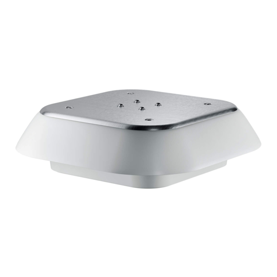
Torrini di estrazione da tetto
in CA e CC - serie TP
I S T R U Z I O N I
D I
M O N T A G G I O
1
Eseguire il foro sul tetto dell'armadio come
da dimensioni riportate nella dima di foratura.
Posizionare il torrino sul foro predisposto
e fissarlo al quadro con le viti di fissaggio
in dotazione.
Serrare le viti con coppia di circa 1,5 Nm.
2
Eseguire l'allacciamento elettrico come riportato
in Fig. A per le versioni in CA, e in Fig. B per le
versioni in CC.
Si consiglia di indossare dispositivi di protezione idonei:
• guanti EN 420 e EN 388 • occhiali di sicurezza EN 166 - 170
A V V E R T E N Z E
Disinserire la tensione prima di eseguire qualsiasi operazione
sul prodotto.
- Eseguire l'allacciamento elettrico nel rispetto delle norme
vigenti e delle prescrizioni locali a tutela della sicurezza
nell'impiego di materiale elettrico;
- L'allacciamento elettrico deve essere eseguito da personale
qualificato;
- L'alimentazione elettrica del prodotto deve rispettare i valori
nominali riportati sull'etichetta.
- Rispettare la polarità come indicato negli schemi
di Fig. A e di Fig. B.
- Le versioni in CC sono di classe III solo se viene utilizzato
un trasformatore di sicurezza oppure un convertitore CA/CC
con avvolgimenti separati, il cui isolamento sia conforme
alle prescrizioni del doppio isolamento o dell'isolamento
rinforzato.
- Output tachimetrica 3 IMPULSI/GIRO.
Il coperchio metallico non deve mai essere rimosso.
Le istruzioni di montaggio sono parte integrante del prodotto.
Devono essere rilasciate a tutti coloro che utilizzano
il prodotto. Non ci assumiamo alcuna responsabilità a fronte
di guasti o malfunzionamenti che dovessero verificarsi per
la mancata osservazione delle istruzioni.
G A R A N Z I A
La garanzia è prestata secondo quanto previsto
dalle "Condizioni generali di vendita".
Tutte le specifiche, i dati ed i disegni riportati possono subire variazioni
senza preavviso.
ENG
EN
AC and DC
roof exhaust units - TP series
M O U N T I N G
I N S T R U C T I O N S
1
Cut the mounting hole on the top of enclosure
using the cut-out dimensions.
Position the roof exhaust unit on the pre-cut
hole and fix it to the enclosure using the fixing
screws supplied. Tighten the screws
with a torque of approx 1.5 Nm (13.28 Lbf.in).
2
Carry out the electrical connection as shown
in Fig. A for AC models and in Fig. B for DC
models.
We recommend the wearing of suitable protective clothing:
• gloves EN 420 and EN 388 • safety glasses EN 166 - 170
A D V I C E
Disconnect the mains supply before carrying out any
operation on the product.
- The electrical connection must be carried out according
to the local norms and safety regulations which govern
the use of electrical material;
- Electrical connection must be carried out by qualified
personnel only;
- The power supply of the product must comply with the
rated values shown on the label.
- Polarity must be respected as indicated in the wiring
diagrams (Fig. A and Fig. B)
- The DC versions are in class III only if a safety isolating
transformer, or a AC/DC convertor with separate windings,
is used, the insulation of which complies with double
insulation or reinforced insulation requirements.
- Tachometer output 3 PULSE/REVOLUTION.
The cover of the mounting frame shall not be removed
from the mounting frame.
The assembly instructions are an integral part of the product.
They must be issued to everyone who works with
the product. We cannot accept any liability for damage
associated with failure to observe these instructions.
W A R R A N T Y
For warranty conditions see "General Sales Conditions".
All specifications, data and drawings are subject to change without notice.
1
2
Fig. A
Fig. B
ref. Fig. B
33K
3.9K
+
PWM
U
10K
-
12V
12V
Speed setting
Air flow setting
Full
Air flow setting
PWM 1-10 kHz
with variable
speed
1V-10V
(DC 10V)
resistance
CUSTOMER CIRCUITS
10K
CONNECTION
PULL-UP
RESISTANCE
Fig. C
OK
NO
IT
PULIZIA E SOSTITUZIONE DEL PANNO
VERSIONI IP54, IP55 NON UL
Attenzione! Togliere tensione dal torrino prima di eseguire le operazioni
elencate in seguito, ed indossare i dispositisi di protezione idonei.
Durante tutte le operazioni il torrino deve essere in posizione orizzontale,
col coperchio rivolto verso l'alto.
A
Rimuovere il coperchio togliendo le 8 viti presenti.
B
Sfilare il panno e la rete metallica, facendo attenzione ai bordi taglienti
della rete.
C
Pulire il panno mediante sciacquatura, trattamento con getto d'acqua
o battitura, oppure sostituire il panno con uno nuovo.
D
Ripetere le operazioni all'inverso per chiudere il torrino, con i seguenti
accorgimenti:
I verificare che durante l'inserimento il panno non si ripieghi su se stesso;
II prima di chiudere il coperchio, verificare che il cavo sia alloggiato
in modo corretto nel passacavo; (vedi Fig. C)
III fissaggio coperchio: la coppia di serraggio deve essere di 1,5 Nm.
Le 4 viti centrali devono essere avvitate contemporaneamente,
un giro alla volta ciascuna;
IV a fine operazioni, verificare che il ventilatore giri senza impedimenti
all'interno del torrino.
La frequenza della sua sostituzione varia in funzione della quantità
di polvere presente e del tempo di funzionamento; va quindi
determinata di volta in volta dall'utilizzatore per ogni singolo impiego.
Il panno filtro sporco diminuisce il rendimento del torrino causando una
insufficiente o, addirittura, totale mancanza di ventilazione.
CLEANING AND REPLACEMENT
EN
OF THE FILTER MEDIA
ONLY FOR NON-UL IP54 AND IP55 VERSIONS
Caution! Disconnect the mains supply before carrying out any operation
on the product and wear the suitable protective clothing.
During all operations the roof exhaust unit must be in horizontal position,
with the top facing upwards.
+ 24
A
Remove the top by unscrewing the 8 screws.
- (GND)
B
Remove the filter media and the wire mesh, be aware of the sharp
CTRL
edges of the mesh.
TACHO
C
Clean the filter media by rinsing, spraying or beating, and eventually
replace it with a new one.
D
Repeat the steps in backward to close the roof exhaust unit, observing
the following measures:
I ensure that the filter media does not fold on itself;
II before closing the top, check that the cable is seated correctly
in its conduit; (see Fig. C)
III fix the top: the tightening torque should be of 1.5Nm (13.28 Lbf.in).
The 4 centre screws should be tightened in measured equal
amounts to prevent distortion;
IV verify that the fan turns freely inside the roof exhaust unit.
The frequency with which the filter media must be replaced depends on
the amount of dust accumulated, operating period, and specific working
conditions encountered by the user.
An unclean filter media reduces the efficiency of the roof exhaust unit
causing insufficient or finally a total lack of ventilation.
Advertisement

Summary of Contents for Fandis TP Series
- Page 1 Rimuovere il coperchio togliendo le 8 viti presenti. Sfilare il panno e la rete metallica, facendo attenzione ai bordi taglienti in CA e CC - serie TP roof exhaust units - TP series della rete. Pulire il panno mediante sciacquatura, trattamento con getto d’acqua...
- Page 2 DIMA DI FORATURA DISEGNO 1:1 CUT OUT DRAWING 1:1 =78 mm (3.07 in)= 5 mm (0.197 in) 175 mm (6.89 in) 189 mm (7.44 in)
Need help?
Do you have a question about the TP Series and is the answer not in the manual?
Questions and answers