Table of Contents
Advertisement
Quick Links
Advertisement
Table of Contents

Summary of Contents for D'Amore Engineering A1500.2
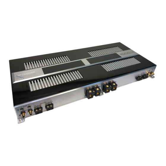
- Page 1 A1500.2 / A1500.4 Mobile Audio Amplifier Owner ’s Manual...
-
Page 2: Table Of Contents
Table of Contents About the design Fuse it Power Requirements Balanced or Unbalanced How do I know what type of source I have The LED Meters The LED Meters and fault conditions How to remove the cover Specifications Dyno Test Results (Birth Certificate) Limited warranty information... -
Page 3: About The Design
About the design When you pick up the 1500.2 / 1500.4, you might realize this amplifier is a bit different than most. The A series amplifiers were originally developed from a Class A home audio amplifier that our founders built for their own personal use. -
Page 4: Fuse It
About the design (cont.) The heat that MOSFETs and transistors create is sucked out of them by using ceramic aluminum oxide wafers between the devices and the solid aluminum billet heatsinks. We want the heat in the heatsinks, not the transistors and MOSFETs. -
Page 5: Power Requirements
2Ω X 4 resistive load, to clipping 147A X 2 Balanced or Unbalanced? The A1500.2 / A1500.4 amplifiers have RCA inputs for unbalanced or balanced (differential) analog audio. Almost all audio source units / DSPs use unbalanced audio output connections. -
Page 6: How Do I Know What Type Of Source I Have
How do I know what kind of source I have? Most likely you have an unbalanced source, in which case no adjustment to the amplifier switches need to be made. The easiest way to know is to use a digital volt/ohm meter. - Page 7 The LED meters (cont.) This way the user has a rough idea of how much power the amplifier is putting out IF the impedance was 8Ω or 4Ω. Since the amplifer is meant to drive various load impedances, and the impedance of the speaker changes depending on the frequency being reproduced, the meters are never actually calibrated “power meters.”...
-
Page 8: The Led Meters And Fault Conditions
The LED meters (cont.) Our meters are calibrated in 3dB steps with the final RED segment indicating the output is near or at clipping. As such in normal use it is okay for the meters to flash red on occasion but if they are solid RED for any length of time the output is probably clipping and the output level should be reduced to avoid speaker damage. - Page 9 If it happens again, please shut the system down and investigate the problem to avoid damage to the amplifier or vehicle. Minimum load impedance for the A1500.2 is 1Ω stereo or 2Ω bridged. Minimum load impedance for the A1500.4 is 2Ω stereo or 4Ω bridged.
-
Page 10: How To Remove The Cover
How to remove the cover The cover can be removed for various reasons. One reason may be to convert the amplifier from unbalanced inputs to balanced (differential) inputs. DO NOT OPERATE AMPLIFIER WITH COVER REMOVED AS HIGH VOLTAGE EXISTS VARIOUS COMPONENTS WHICH WILL BITE YOU IF YOU TOUCH THE WRONG 2 THINGS AT THE SAME TIME 1. -
Page 11: Specifications
Specifications A1500.2 A1500.4 CTA 2006-C Power Ratings 4Ω 350 x 2 325 x 4 2Ω 650 x 2 500 x 4 1Ω 1000 x 2 ---------- 4Ω Bridged 1350 x 1 1000 x 2 2Ω Bridged 2000 x 1 ---------- D’Amore Engineering Ratings... - Page 12 Specifications (cont.) Dimensions, inches 23.25 x 11.0 x 2.25 Dimensions, mm 590 x 280 x 57 Weight, Lbs. / kg 27.7 / 12.6...
-
Page 13: Dyno Test Results (Birth Certificate)
TEST RESULTS DURING PRODUCTION THIS AMPLIFIER SERIAL # _____________________ AD-1 Amplifier Dyno Test Results @14.4V Certified Power 4Ω Certified Power 2Ω Certified Power 1Ω Certified Power 4Ω Bridged Certified Power 2Ω Bridged Dynamic Power 4Ω Dynamic Power 2Ω Dynamic Power 1Ω Dynamic Power 4Ω... -
Page 14: Limited Warranty Information
Limited Warranty D’Amore Engineering warrants this product to be free of defects in materials and workmanship for a period of one year. This warranty is not transferrable and applies only to the original purchaser from an authorized D’Amore Engineering dealer. Should service be necessary under this warranty for any reason due to manufacturing defect or malfunction, D’Amore Engineering will (at its discretion) repair or replace the defective product with new or remanufactured product at... - Page 16 D’Amore Engineering A Series Amplifiers Owner’s Manual Rev. 2 2020 Printed in Camarillo, California USA...
Need help?
Do you have a question about the A1500.2 and is the answer not in the manual?
Questions and answers