Advertisement
Quick Links
Advertisement

Summary of Contents for RS PRO WT280x
- Page 1 Internal ENGLISH High Speed 3D Printer rspro.com File No.: VersionA1...
- Page 2 Internal Notes: This manual includes the important information regarding the installation, operation, maintenance and storage of the product. Please read carefully prior to using; During printing, do not touch the power cable, USB cable or remove the USB flash drive, as this will cause interruption to printing which will result in potential damage to the printer;...
- Page 3 Internal in you being burnt or injured; Children must be supervised while using this machine, unsupervised use may result in injury; This Manual is protected by copyright and this Company shall reserve the final interpretation right. Without the authorization; This Company has the rights to alter the content relating to this type of printer and in its operation manual without the prior separate notification.
-
Page 4: Basic Parameter
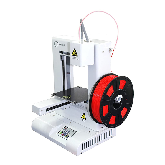
Internal 1. Diagram of Product 2. Basic Parameter Printing Parameter: Software parameter: Type High Speed 3D Printer Slicing software REALvision Quantity of Slicing file format Nozzle Diameter of 0.4mm Printing format .fcode Nozzle Printing page Computer 0.1mm~0.4mm Windows XP/Vista/7/8/10 thickness operation system File No.:... -
Page 5: Unpacking List
Internal Printing Language switch Support multi-language ±0.1mm precision Printing speed 20~450mm/s Operating conditions: Printing material HS / PLA Temperature 5 °C - 35 °C Printing method SD card/USB drive Humidity 30%-90% Temperature of 190~260℃ Power adapter: nozzle Temperature of Input 30~80℃... - Page 6 Internal Power Power cable adapter USB2.0 Magnetic printer USB printing cable platform A Cutting External fan nippers USB flash Screws drive Spool Filament Tube holder Hex key Tweezers HS Filament identification sticker Five Quick Guides (German/Engl ish/French/Ita lian/Spanish) File No.: VersionA1 r r sp spr r o.c o.com...
-
Page 7: Installation Of Equipment
Internal 4. Installation of Equipment a) Power connection 1)Connect the mains cable to the power supply and then connect the power cable to the 3D printer. 2) Plug the mains plug into a mains socket. 3) Switch the printer on. b) Install the Spool holder: Unscrew the central two screws on the right side with the hex key provided, place the spool holder in the position shown below and then replace the screws, tighten the screws until the holder is held securely. - Page 8 Internal d) Install the Filament Tube: Take the filament tube insert one end in the black ring on right side as shown, leave the other end free. e) Installing the print bed Place the bed on the printer as shown below. Use the 4 provided bull clips to secure the bed to the printer, taking care to ensure that the platform and bed are clear of obstacles.
- Page 9 Internal f) Place the printing materials Place the filament on spool holder as shown below, pass the filament through the filament tube until there is approximately 5cm of filament exposed. 5. Introduction of Touch Screen Operation Function Start-up interface :Select this option to enter the printing interface, where it is possible select the file that is to be printed and confirm.
- Page 10 Internal 1. Printing interface :Current selection :Scroll down :Return to the main page 2. Material-changing interface :Upward arrow is used to increase the temperature : Downward arrow is used to reduce the temperature : Left facing arrow is used to return to the previous menu :...
- Page 11 Internal :This option is used to adjust the temperature on the extruder head and the print bed. 3.1 Extrusion head and platform temperature-rising interface :Upward arrow is used to increase the temperature :Downward arrow is used to reduce the temperature :Left facing arrow is used to return to the previous menu :After setting the target temperature, click “√”...
- Page 12 Internal :Select this option to enter the printing testing operation, this is used to test whether the temperatures and printing functions are performing within specification :Left facing arrow is used to return to the previous menu 4.2 Language set-up interface :Enter this option to switch to the required language, using the down arrow until the correct language is selected :Left facing arrow is used to return to the previous menu...
- Page 13 Internal Follow the instructions on the screen, tighten all leveling nuts as instructed. After tightening, loosen the screw one rotation, then press the next button “ ” to move onto the next step. Use the up/down arrows ( / ) on the screen to adjust the gap between the print bed and the nozzle leaving a 1mm gap.
- Page 14 Internal The next step is to adjust the platform to ensure it is level. ① Using a leveling card or an A4 piece of paper, place the paper/card on the print bed under the nozzle, moving the paper/card back and forth, while adjusting the nut corresponding to the nozzle under the print bed. The nut adjustment will move the print bed up or down, keep adjusting until there is a slight friction when moving the paper between the print bed and the nozzle.
- Page 15 Internal 7. Material-Changing Click “ ” to enter the material-changing interface Press “ ”until the target temperature reaches 215℃, then click “ ”to start the extruder heating. Once the target temperature has been reached, the printer will carry out several steps automatically. The printer will then request the removal of the filament, manually remove the filament from the nozzle hole and click “...
- Page 16 Internal Return to the Heating interface, if necessary, click “ ”to move on to the next step. If the extruder temperature is still at the set temperature, the printer will skip step 7 and automatically go to step 8. Insert the filament into the feeding hole as shown in the first image below, click“ ”...
- Page 17 Internal Adjust the target temperature of print head from “100℃” to “215℃”, the target temperature of print bed will show “ ” (as per image below). Click “ ” to start the heating process. Click “ ” to return to the previous screen once the extruder has reached the required temperature.
- Page 18 Internal ② When feeding or retracting the filament, pay attention to the temperature of the extruder, if the temperature drops below the melt point of the filament, the filament will get stuck in the extruder. ③ After returning to the movement interface, feed the filament immediately as the temperature will start to reduce if the printer is left to idle.
- Page 19 Internal 9. Install RV Software Identify “REALvision_Setup” installation package in the delivered USB drive and double click the icon to open. Select the required installation language in the new pop-up window, and then click “OK” to enter the next step. Select “Next”...
- Page 20 Internal Select “I Agree” to enter the next step. Select “Next ” File No.: VersionA1 r r sp spr r o.c o.com...
- Page 21 Internal To use the default installation location, click “Next”. If it is required to install to a different location, please click the “Browse” button, navigate to the selected location, and click the “Next” button after the installation location is selected. Select “Install”...
- Page 22 Internal When the pop up prompt window asks “Whether activate software now”, select “Yes” File No.: VersionA1 r r sp spr r o.c o.com...
- Page 23 Internal Select “Retype your product key” 10) Open the “Code” text in the installation program file, copy the activation code and paste in the “Product Key” box, and then click the “Next Step” File No.: VersionA1 r r sp spr r o.c o.com...
- Page 24 Internal 11) It indicates the activation is successful, and click “Complete” 12) Click “Finish”, the software installation is now complete. There will be a prompt about updating when opening for the first time, select “Yes” to update and select “No” to not update temporarily. File No.:...
- Page 25 Internal Description of RV Software Interface Icons 1) How to import the printing files Click the file icon “ ”, identify the file needs to be printed and sliced in the pop-up window and double click. 2) Download the model base Click the download icon “...
-
Page 26: Print Setup
Internal 3) Print setup Click the setup icon “ ” to enter the setup window. This area is used to adjust the layer thickness, filling rate, shell thickness, print temperature, print bed temperature, language etc. It is advisable to use the recommended setup in the beginning. - Page 27 Internal In the advanced setup, it is possible to adjust the speed, extrusion flow, support parameters etc. It is advisable to use the default parameters. 4) Check slicing effect Click the slicing icon “ ” to display the slicing diagram. It is possible to check the specific effects (including the support) through pull the progress bar.
- Page 28 Internal 5) Connect printer or export file for printing (It is advised to use USB drive facilitate the printing, which is also the off-line USB drive printing method) On line (network) printing: ① Click the print icon “ ” to pop up the new window ②...
- Page 29 Internal Label 5 is for adjusting the height of platform Label 6 is the feeding and discharging of extrusion head, it is only able to operate after the temperature of extrusion head is increased Label 7 is the moving value, it is the moving distance between platform and extrusion head after clicking. This value can be adjusted Label 8 is time Label 9 is the temperature indicated for platform and extrusion head...
- Page 30 Internal ② The new pop-up window is the location that the file needs to be saved, click “Save” after confirming the location and file name ③ Insert USB drive into the computer, copy the exported file to USB drive. Once the file is copied, take the USB drive from the computer and insert in the port of printer, select the file that needs to be printed, the printer will then be able to start printing.
- Page 31 Internal ③ Reset and return to the parameters before being changed. 7) Zoom in/out mode ① Click the zoom icon “ ” and input the required proportion or dimension in any box below to change the size of model. Please note that, it is only required to adjust one of the parameters, and the other parameters will also be changed as per the proportion;...
- Page 32 Internal 9) Mirror Click the icon “ , then click the corresponding axis which is to be mirrored. 10) Support Click the icon “ , to decide whether to add support and which type of support according to the model type.
- Page 33 Internal 12) Delete Delete one model or delete all models. A new prompt window will pop up and click "Yes". 13) Model merging After importing 2 or more models, select "Edit-select all Models" from the menu bar or select all models directly by using the keyboard "Ctrl+ A"...
- Page 34 Internal 2)Click the button"+" on the new setting window to add layer, set the slice number and thickness in the corresponding box at the beginning and end, and close the window after setting. 3)Click the "Display Slice" icon to preview the thickness of the Settings File No.:...
- Page 35 Internal 15) Stop/start slicing The model can be sliced automatically by default when imported. It is suggested to switch this off and to only slice once the model has been adjusted, then start slicing. 16) REALview Icon 1: Reset the camera Icon 2: Start and End Icon 3: Reset the model after being adjusted in the model area File No.:...
- Page 36 Internal Usage of REALview Notes for AR experience: The computer needs to have the camera Open the RV software and select "Help →REALview Help → Load REALview Focus into the workspace" from the menu bar or directly import the "AR prop" file from the USB flash drive. After importing the model on the USB drive, use 3D printer to print out;...
-
Page 37: First Print
Internal Click the icon “ ” at the left bottom of software to start; Point the item against camera with the distance of about 25CM. Move the item and observe the model on screen, and the model will be changed along with turning the item. Click the icon “... -
Page 38: Printer Failure
Internal Open RV slicing software → select "Open model" → select a file → Follow the steps of "10.5. B. Offline copy to USB drive for printing" to save Fcode 2)Print Insert the USB drive → select "Print" → select the file to print → Confirm Printing Failure Troubleshooting 1)Failure of printing model: Open RV software, and click “Help”... - Page 39 Internal Solution: A. Check whether the thermal line of extrusion head is disconnected or has a loose connection B. The thermocouple is damaged and replace with the new thermocouple Failure 2: The screen prompts to report error “ERROR 145 Temperature Control” Solution: A.
- Page 40 Internal Please start the machine first and then insert the USB drive Disassembly and assembly of Extruder Head Wait until the nozzle has cooled down. Use the hex key to unscrew the screws and take off the extruder head cover (If there is any filament in the extrusion head hole, please cut off the filament) Undo the screws holding the extrusion head Unplug the terminal as shown (In order to facilitate the operation, it is advised to unplug for the new operators)
- Page 41 Internal Remove the screws connected to the fan, remove the fan, and pay attention to protecting the fan cables. Remove the screws on both sides Check whether there is any broken materials or other crushed materials inside File No.: VersionA1 r r sp spr r o.c o.com...
- Page 42 Internal If there is no other problem, raise the temperature of heating block to 230℃ after connecting the extrusion head to power cable. Poke the filament in tube with tools to enable the filament to be squeezed out from the nozzle;...
- Page 43 Internal Install the cooling fin and tighten with screws. Please note that the cooling fin needs to be in the right position when twisting the screws prior to tightening as below diagram. × √ 10) Install the fan 11) Plug the terminal on cable File No.:...
- Page 44 Internal 12) Install the extrusion and tighten with screws 13) Install the extrusion head cover and tighten with screws File No.: VersionA1 r r sp spr r o.c o.com...
- Page 45 Internal File No.: VersionA1 r r sp spr r o.c o.com...
Need help?
Do you have a question about the WT280x and is the answer not in the manual?
Questions and answers