Advertisement
Available languages
Available languages
Quick Links
STYLE SELECTIONS and logo design are trademarks
or registered trademarks of LF, LLC.
All Rights Reserved.
Serial Number ____________________________ Purchase Date _________________________
Questions, problems, missing parts? Before returning to your retailer, call our
customer service department at 1-877-888-8225, 8 a.m. - 8 p.m., EST, Monday - Sunday.
VR20276
ITEM #2593021/ #2808041/ #2808042
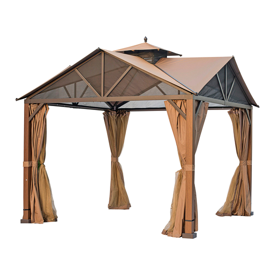
GABLED SOFT-TOP
MODEL
#TPGAZ2307/ #TPGAZ2307A/ #TPGAZ2307B
1
GAZEBO
Español p. 22
Advertisement

Subscribe to Our Youtube Channel
Summary of Contents for Style selections TPGAZ2307
- Page 1 ITEM #2593021/ #2808041/ #2808042 GABLED SOFT-TOP GAZEBO STYLE SELECTIONS and logo design are trademarks MODEL #TPGAZ2307/ #TPGAZ2307A/ #TPGAZ2307B or registered trademarks of LF, LLC. All Rights Reserved. Español p. 22 Serial Number ____________________________ Purchase Date _________________________ Questions, problems, missing parts? Before returning to your retailer, call our customer service department at 1-877-888-8225, 8 a.m.
-
Page 2: Package Contents
PACKAGE CONTENTS QUANTITY PART DESCRIPTION QUANTITY PART DESCRIPTION Hook Connection Tube Center Device Small Top Frame Long Small Top Bracing Small Canopy Tube Short Small Top Bracing Small Canopy Connection Frame Small Netting Decorative Ball... - Page 3 PACKAGE CONTENTS DESCRIPTION QUANTITY QUANTITY PART PART DESCRIPTION Left Bracing Long Top Bar Right Bracing Roof Tube Connector Middle Beam Middle Vertical Beam Big Canopy Middle left Bracing Triangle Netting Middle Right Bracing...
- Page 4 PACKAGE CONTENTS QUANTITY QUANTITY PART DESCRIPTION DESCRIPTION PART Post Beam Connector Decorative Cover Left Support Bar Top Bar Connector Right Support Bar Left Beam Base Right Beam Base Cover Curtain Protection Corner Netting Tube Mosquito Net Netting Tube Connector...
- Page 5 HARDWARE CONTENTS (shown actual size) Flat Washer Qty. 252 + 10 Extra × t l o Qty. 212 + 6 Extra Handle Screw Qty.8 + 1 Extra × t l o Qty. 8 + 1 Extra M6 × 55 mm Bolt Qty.
-
Page 6: Safety Information
SAFETY INFORMATION Please read and understand this entire manual before attempting to assemble, operate or install the product. WARNING • Maximum load for the roof hook: 26 lbs. • WARNING: KEEP ALL FLAME AND HEAT SOURCES AWAY FROM THIS TENT FABRIC. This tent meets the CPAI-84 flammability requirements. - Page 7 ASSEMBLY INSTRUCTIONS 1. Slide the Base Cover (O2) over the bottom of the Post (A) and connect the Base (O1) to the Post (A) with Bolt (AA) plus Flat Washer (FF). Add Bolt Cover (GG). Repeat for all four posts. Hardware Used M6 x 15 mm Bolt Flat Washer...
- Page 8 ASSEMBLY INSTRUCTIONS 3. Connect the Netting Tube Connector (F) to the beam with Bolt (AA), Flat Washer (FF) and Bolt Cover (GG). Hardware Used M6 x 15 mm Bolt Flat Washer Bolt Cover Wrench...
- Page 9 ASSEMBLY INSTRUCTIONS 4. Connect the assembled Beam (C1/C2) to the Post (A), attach with Bolt (AA), Flat Washer (FF) and Bolt Cover (GG). Stand the assembled structure of posts (A) and beams (C1/C2) up with two people. Repeat for opposite side and add two side beams to complete four sided structure.
- Page 10 ASSEMBLY INSTRUCTIONS 5. Connect the Beam (B1/B2) to the Post (A) and the Beam (C1/C2) respectively by Bolts (AA), Flat Washer (FF) and Bolt Cover (GG). Hardware Used M6 x 15 mm Bolt Flat Washer Bolt Cover Wrench 6. Insert one end of the Netting Tube (E) into the Netting Tube Connector (F), fix the other end onto the beam with Bolt (BB), Flat Washer (FF) and Plastic...
- Page 11 ASSEMBLY INSTRUCTIONS 7.1. Connect the Top Bar Connector (N) to the post (A) by Bolt (AA), Flat Washer (FF) and Bolt Cover (GG). 7.2. Put the Protection Corner (D) over the corner of the Left Beam (C1) and the Right Beam (C2), and tighten it by Bolt (AA), Flat Washer (FF) and Bolt Cover (GG).
- Page 12 ASSEMBLY INSTRUCTIONS 9.1. Assemble the two Small Top Frame (R), connect all the Small Top Connecting Frame (P3) to the Small Top Frame (R) respectively, then tighten them by Bolt (AA), Flat Washer (FF) and Bolt Cover (GG). 9.2. Attach the Connection Frame (P3) to the Connection Tube(Q) by Bolt (AA), Flat Washer (FF) and Bolt Cover (GG).
- Page 13 ASSEMBLY INSTRUCTIONS 10. Insert the Long Top Bar (J) into the Small Top Frame (R), and attach with Bolt (AA), Flat Washer (FF) and Bolt Cover (GG), place the other end of the Long Top Bar (J) through the Top Bar Connect (N) and attach with Bolt (EE), Flat Washer (FF), Nut (HH), Bolt Cover (GG) and Cap (II).
- Page 14 ASSEMBLY INSTRUCTIONS 11.1. Connect one end of the Middle Vertical Beam (H2) to the Decorative Cover (K) by Bolt (AA), Flat Washer (FF) and Bolt Cover (GG), connect the other end to the Connect (M) by Bolt (AA), Flat Washer (FF) and Bolt Cover (GG).
- Page 15 ASSEMBLY INSTRUCTIONS 12. Connect one end of the Left Bracing (G1) and Right Bracing (G2) to the Beam (C1/C2), by Bolts (DD), connect the other end of (G1/G2) to the Connector (M) by Bolts (AA), Flat Washer (FF) and Bolt Cover (GG). Hardware Used M6 x 15 mm Bolt M6 x 15 mm Bolt...
- Page 16 ASSEMBLY INSTRUCTIONS 14. Place the Big Canopy (T) over the assembled frame. NOTE: No need to tension the canopy at this step. 15. Connect the Small Top Bracing (P1/P2) to the Central Device (P), cover the Small Canopy (S) onto the small top, and the Decorative Ball (P4) over the Central Device (P).
- Page 17 ASSEMBLY INSTRUCTIONS 16.1. Insert the assembled small top bracing (P1) into the top of the connection tube, attach them by Bolt (AA), Flat Washer (FF) and Bolt Cover (GG). 16.2. Connect the small top bracing (P2) to the connection frame by Bolt (KK) and Nut (HH), Cap (II) and Bolt Cover (GG).
- Page 18 ASSEMBLY INSTRUCTIONS 18. Install the Small Netting (S1) onto the outside of the Connection Frame (P3) by felts, connect the two Small Netting (S1) by felts. Note: The small netting should be installed outside of the connection frame. 19. Fix the Triangle Netting (W) onto the velcro tapes which are pasted on the inside of the shelf.
- Page 19 ASSEMBLY INSTRUCTIONS 20. Hang the Curtain (U) to the inside of the netting tube by using the hanger (MM) and the Mosquito Net (V) to the outside of the netting tube Hardware Used Ring 21. Insert the Stake (OO) into the ground through the Base (O1).
-
Page 20: Care And Maintenance
CARE AND MAINTENANCE • For cleaning, use a mild detergent solution, rinse with water, and allow to air dry. Do not use acetone, abrasive, or other special detergents as they would be harmful to the product’s finish. • Due to the nature of steel, surface oxidation (rusting) will occur if this protective coating is scratched. This is a natural process. -
Page 21: Replacement Parts List
REPLACEMENT PARTS LIST 1-877-888-8225 For replacement parts, call our customer service department at , 8 a.m. - 8 p.m., EST, Monday - Sunday. Washer M6 × 15 mm Bolt Handle Screw M6 × 15 mm Bolt M6 × 55 mm Bolt M6 ×... - Page 22 ARTÍCULO #2593021/ #2808041/ #2808042 GAZEBO DE CUBIERTA SUAVE CON GABLETE STYLE SELECTIONS y el diseño del logo son marcas MODELO #TPGAZ2307/ #TPGAZ2307A/ #TPGAZ2307B comerciales o marcas registradas de LF, LLC. Todos los derechos reservados. Número de serie _________________________ Fecha de compra _________________________ ¿Preguntas, problemas, piezas faltantes? Antes de volver a la tienda, llame a nuestro...
- Page 23 CONTENIDO DEL PAQUETE CANTIDAD PIEZA DESCRIPCIÓN CANTIDAD PIEZA DESCRIPCIÓN Gancho Tubo de conexión Estructura superior Dispositivo central pequeña Refuerzo superior Tubo de toldo pequeño pequeño largo Refuerzo superior Toldo pequeño pequeño corto Red pequeña Estructura de conexión Bola decorativa...
- Page 24 CONTENIDO DEL PAQUETE CANTIDAD CANTIDAD PIEZA DESCRIPCIÓN PIEZA DESCRIPCIÓN Refuerzo izquierdo Barra superior larga Refuerzo derecho Tubo del techo Conector Viga central Viga vertical central Toldo grande Refuerzo central izquierdo Red triangular Refuerzo central derecho...
- Page 25 CONTENIDO DEL PAQUETE CANTIDAD CANTIDAD PIEZA DESCRIPCIÓN PIEZA DESCRIPCIÓN Poste Conector de viga Cubierta decorativa Barra de soporte izquierda Conector de barra Barra de soporte derecha superior Viga izquierda Base Viga derecha Cubierta de la base Cortina Esquina de protección Tubo de red Mosquitero Conector de tubo de red...
- Page 26 ADITAMENTOS (se muestran en tamaño real) Arandela plana Cant. 252 + 10 adicionales Perno M6 x 15 mm Cant. 212 + 6 adicionales Tornillo de la manija Cant. 8 + 1 adicional Perno M6 x 15 mm Cant. 8 + 1 adicional Perno M6 x 55 mm Cant.
-
Page 27: Información De Seguridad
INFORMACIÓN DE SEGURIDAD Lea y comprenda por completo este manual antes de intentar ensamblar, usar o instalar el producto. ADVERTENCIA • Carga máxima para el gancho del techo: 11,79 kg. • ADVERTENCIA: MANTENGA LA TELA DE LA TIENDA ALEJADA DE LAS LLAMAS Y LAS FUENTES DE CALOR. -
Page 28: Instrucciones De Ensamblaje
INSTRUCCIONES DE ENSAMBLAJE 1. Pase la cubierta para base (O2) sobre la parte inferior del poste (A) y conecte la base (O1) al poste (A) con el perno (AA) más la arandela plana (FF). Agregue la cubierta para perno (GG). Repita la operación en los cuatro postes. - Page 29 INSTRUCCIONES DE ENSAMBLAJE 3. Conecte el conector del tubo de red (F) a la viga con el perno (AA), la arandela plana (FF) y la cubierta para perno (GG). Aditamentos utilizados Perno M6 x 15 mm Arandela plana Cubierta para perno Llave inglesa...
- Page 30 INSTRUCCIONES DE ENSAMBLAJE 4. Conecte la viga ensamblada (C1/C2) al poste (A), fije con el perno (AA), la arandela plana (FF) y la cubierta para perno (GG). Con dos personas, levante la estructura ensamblada de postes (A) y vigas (C1/C2). Repita en el otro lado y agregue dos vigas laterales para completar la estructura de cuatro lados.
- Page 31 INSTRUCCIONES DE ENSAMBLAJE 5. Conecte la viga (B1/B2) al poste (A) y la viga (C1/C2) respectivamente con los pernos (AA), la arandela plana (FF) y la cubierta para perno (GG). Aditamentos utilizados Perno M6 x 15 mm Arandela plana Cubierta para perno Llave inglesa 6.
- Page 32 INSTRUCCIONES DE ENSAMBLAJE 7.1. Conecte el conector de la barra superior (N) al poste (A) con el perno (AA), la arandela plana (FF) y la cubierta para perno (GG). 7.2. Coloque la esquina de protección (D) sobre la esquina de la viga izquierda (C1) y la viga derecha (C2), y apriételas con el perno (AA), la arandela plana (FF)
- Page 33 INSTRUCCIONES DE ENSAMBLAJE 9.1. Ensamble las dos estructuras superiores pequeñas (R), conecte todas las estructuras de conexión superiores pequeñas (P3) a la estructura superior pequeña (R) respectivamente, luego apriételas con el perno (AA), la arandela plana (FF) y la cubierta para perno (GG). 9.2.
- Page 34 INSTRUCCIONES DE ENSAMBLAJE 10. Inserte la barra superior larga (J) en la estructura superior pequeña (R) y fije con el perno (AA), la arandela plana (FF) y la cubierta para perno (GG), pase el otro extremo de la barra superior larga (J) por la conexión de la barra superior (N) y fije con el perno (EE), la arandela plana (FF), la tuerca (HH), la cubierta para perno...
- Page 35 INSTRUCCIONES DE ENSAMBLAJE 11.1. Conecte un extremo de la viga vertical central (H2) a la cubierta decorativa (K) con el perno (AA), la arandela plana (FF) y la cubierta para perno (GG), conecte el otro extremo a la conexión (M) con el perno (AA), la arandela plana (FF) y la cubierta para perno (GG).
- Page 36 INSTRUCCIONES DE ENSAMBLAJE 12. Conecte un extremo del refuerzo izquierdo (G1) y el refuerzo derecho (G2) a la viga (C1/C2), con los pernos (DD), conecte el otro extremo de (G1/G2) al conector (M) usando los pernos (AA), la arandela plana (FF) y la cubierta para perno (GG).
- Page 37 INSTRUCCIONES DE ENSAMBLAJE 14. Coloque el toldo grande (T) sobre la estructura ensamblada. NOTA: no es necesario tensar el toldo en este paso. 15. Conecte el refuerzo superior pequeño (P1/P2) al dispositivo central (P), cubra el toldo pequeño (S) en la parte superior pequeña y la bola decorativa (P4) sobre el dispositivo central (P).
- Page 38 INSTRUCCIONES DE ENSAMBLAJE 16.1. Inserte el refuerzo superior pequeño ensamblado (P1) en la parte superior del tubo de conexión, fíjelos con el perno (AA), la arandela para perno (FF) y la cubierta para perno (GG). 16.2. Conecte el refuerzo superior pequeño (P2) a la estructura de conexión con el perno (KK) y la tuerca (HH), la tapa (II) y la cubierta para...
- Page 39 INSTRUCCIONES DE ENSAMBLAJE 18. Instale la red pequeña (S1) en el exterior de la estructura de conexión (P3) con fieltros, conecte las dos redes pequeñas (S1) con fieltros. Nota: la red pequeña debe instalarse fuera de la estructura de conexión. 19.
- Page 40 INSTRUCCIONES DE ENSAMBLAJE 20. Cuelgue la cortina (U) en el interior del tubo de la red usando el colgador (MM) y el mosquitero (V) en el exterior del tubo de red. Aditamentos utilizados Anillo 21. Inserte la estaca (OO) en el suelo a través de la base (O1).
-
Page 41: Cuidado Y Mantenimiento
CUIDADO Y MANTENIMIENTO • Para la limpieza, use una solución de detergente suave, enjuáguela con agua y deje que se seque al aire. No use acetona, productos abrasivos u otros detergentes especiales porque dañarían el acabado del producto. • Debido a la naturaleza del acero, puede producirse una oxidación superficial si este recubrimiento protector se raya. -
Page 42: Lista De Piezas De Repuesto
LISTA DE PIEZAS DE REPUESTO Para obtener piezas de repuesto, llame a nuestro Departamento de Servicio al Cliente al 1-877-888-8225, de lunes a domingo de 8 a.m. a 8 p.m., hora estándar del Este. Arandela plana Perno M6 x 15 mm Tornillo de la manija Perno M6 x 15 mm Perno M6 x 55 mm...
Need help?
Do you have a question about the TPGAZ2307 and is the answer not in the manual?
Questions and answers
Need to replace the canopy. Are there any instructions on how to do this? Model #TPGAZ2307
To replace the canopy for the Style Selections gazebo model TPGAZ2307, follow these steps:
1. Use Only Compatible Canopy: Ensure the replacement canopy is specifically made for Item# 2593021, 2808041, or 2808042; Model# TPGAZ2307, TPGAZ2307A, or TPGAZ2307B. Other models are not compatible.
2. Place the Big Canopy: Lay the large canopy (marked as T) over the assembled gazebo frame. Do not tension it at this stage.
3. Assemble the Small Top:
- Connect the small top bracing parts (P1 and P2) to the central device (P).
- Place the small canopy (S) over the small top frame.
- Install the decorative ball (P4) on top of the central device (P).
4. Secure the Small Top:
- Insert the assembled small top bracing (P1) into the connection tube (Q), and attach using Bolt (AA), Flat Washer (FF), and Bolt Cover (GG).
- Connect the bracing (P2) to the connection frame (P3) using Bolt (KK), Nut (HH), Cap (II), and Bolt Cover (GG).
5. Final Adjustments: Once all parts are secured, adjust the canopy for proper fit and appearance.
Note: The replacement includes only the canopy with air vent. The metal frame and triangle nets are not included.
This answer is automatically generated
@Mr. Anderson Is there a video that will help me?