Advertisement
Quick Links
Advertisement

Related Manuals for usi Azure

Summary of Contents for usi Azure
- Page 1 Azure Sphere Module Daniel Tu User Guide V1.0 WCS/WP1 Jun. 3rd, 2020...
- Page 2 Outline MT3620 Setup Nordic nRF52 BLE Setup BLE-based Wi-Fi setup sample Private Ethernet sample Nordic BLE DFU Additional - FTDI Programming Configuration - FCC/IC Cert Statement © USI. All rights reserved.
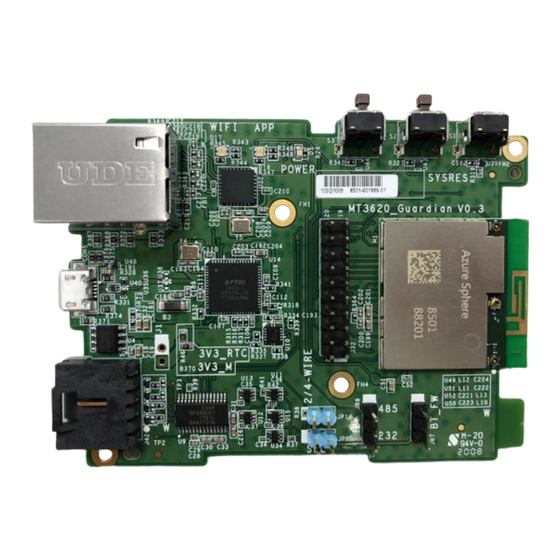
- Page 3 Azure Sphere Carrier Board MT3620_Guardian Rev:0.3 WiFi External Antenna BLE External Antenna © USI. All rights reserved.
- Page 4 MT3620 Interface MT3620_Guardian Rev:0.2 MT3620 GPIO APP RED GPIO45 APP GREEN GPIO46 APP BLUE GPIO47 WIFI RED GPIO48 WIFI GREEN GPIO14 WIFI BLUE GPIO11 BUTTON MT3620 GPIO GPIO12 GPIO13 © USI. All rights reserved.
- Page 5 (SP336E RS232 RTS/ RS485 Enable) Link JP13 PIN 3 GPIO2 RS485 Half Duplex : Link Pin1 and Pin2 of JR8. (GPIO2 pull High for TX, pull low for RX ) Link JP13 Link JP14 © USI. All rights reserved.
- Page 6 MT3620 UART Function MT3620 UART Description ISU0 For Ethernet(ENC28J60) using ISU1 Header J32 pin 13,14,15,16 ISU2 FTDI(FT4232HQ) Port-A ISU3 RS232/RS485 (SP336E) ISU4 Nordic BLE nRF52 UART function © USI. All rights reserved.
- Page 7 MT3620 Setup Steps Follow steps let Visual Studio can download and run debugger to Azure Sphere (MT3620) Install Azure Sphere SDK and Tools Verify Azure Sphere SDK Installation Verify TAP-Windows Adapter Configuration Create tenant and claim your device ...
- Page 8 Install the Azure Sphere SDK Preview for Visual Studio https://aka.ms/AzureSphereSDKDownload Azure Sphere SDK only support on Windows 10, version 1607 Update or later Read Microsoft Installation Guide for more details. https://docs.microsoft.com/en-us/azure-sphere/install/install-sdk © USI. All rights reserved.
- Page 9 Verify Azure Sphere SDK Installation After install SDK, connect the MT3620 guardian board to the PC by USB. Open Device Manager and look for TAP-Windows Adapter V9. And three new COM ports. The numbers on your COM ports may be ...
- Page 10 Verify TAP-Windows Adapter Configuration Check the Network connection Azure Sphere (TAP-Windows Adapter V9) is connected. Right-click on Azure Sphere and check it’s properties are as shown below: © USI. All rights reserved.
- Page 11 Create tenant and claim your device Sign in to Azure Sphere, using a Microsoft account: azsphere login If you've never logged in to Azure Sphere before, add the --newuser parameter along with your Microsoft account email address: azsphere login --newuser <email-address> ...
- Page 12 Connection state : connected Security state : psk Frequency : 2442 Mode : station Key management : WPA2-PSK WPA State : COMPLETED IP Address : 192.168.1.15 MAC Address : 52:cf:ff:3a:76:1b Command completed successfully in 00:00:01.3976308. Reference : https://docs.microsoft.com/en-us/azure-sphere/install/configure-wifi © USI. All rights reserved.
- Page 13 Prepare development and debugging Make sure that your Azure Sphere device is connected to your PC, and your PC is connected to the internet. In an Azure Sphere Developer Command Prompt window, type the following command: azsphere device enable-development ...
- Page 14 Real-time capable applications (RTApps) run on bare metal or with a real-time operating system (RTOS) on the real-time cores A high-level application is required for every Azure Sphere device; RTApps are optional. © USI. All rights reserved.
- Page 15 Start Visual Studio and go to File>Open>CMake to open Samples\GPIO\GPIO_HighLevelApp\CMakeLists.txt Edit the AzureSphereTargetHardwareDefinitionDirectory and AzureSphereTargetHardwareDefinition fields in the CMakeSettings.json file. For example: "AzureSphereTargetHardwareDefinitionDirectory": "<path to cloned samples>\Hardware\ usi_mt3620_bt_evb" "AzureSphereTargetHardwareDefinition": "usi_mt3620_bt_evb.json “ https://github.com/Azure/azure-sphere-samples/tree/master/Hardware Reference : https://docs.microsoft.com/en-us/azure-sphere/install/qs-blink-application © USI. All rights reserved.
- Page 16 (HLCore) from the menu bar or press F5. LED APP on the MT3620 guardian board begins blinking red. Push button S2 to cycle the blink interval between three possible values. By default, the Output window shows output from Device Output © USI. All rights reserved.
- Page 17 Set Up Hardware For Real-time App Make sure that your Azure Sphere device is connected to your PC, and your PC is connected to the internet. Right-click the Azure Sphere Developer Command Prompt shortcut and select More>Run as administrator. When the window opens, issue the...
- Page 18 On the CMake menu (if present), click Build All. If the menu is not present, open Solution Explorer, right-click the CMakeLists.txt file, and select Build. The output location of the Azure Sphere application appears in the Output window. © USI. All rights reserved.
- Page 19 The connected terminal emulator should display output from the HelloWorld_RTApp_MT3620_Baremetal program. The program sends the following words at one-second intervals: Tick Tock Use the debugging options in Visual Studio to set breakpoints, inspect variables, and try other debugging tasks. © USI. All rights reserved.
- Page 20 Nordic nRF52 BLE Setup © USI. All rights reserved.
- Page 21 OS: Linux /Mac OS Install GCC Install nRF5 Command Line Tools Download nRF52 SDK SEGGER J-Link connect to MT3620 EVB by SWD interface Build and download sample Start Debugger © USI. All rights reserved.
- Page 22 Download and install GCC https://gcc.gnu.org/ In Ubuntu OS, you can type below command: $ sudo apt-get install gcc Download gcc-arm-none-eabi-6-2017-q2-update https://developer.arm.com/open-source/gnu-toolchain/gnu-rm/downloads Extract gcc-arm-none-eabi-6-2017-q2-update.tar.bz2 to /usr/local/ Path : /usr/local/gcc-arm-none-eabi-6-2017-q2-update/ © USI. All rights reserved.
- Page 23 Tools Untar nRF5 Command Line Tools and set to $PATH Add nRF5 Command Line Tools path to .bash_profile. $ echo export PATH=“< nRF5 Command Line Tools path >:$PATH" >> ~/.bash_profile © USI. All rights reserved.
- Page 24 Download nRF52 SDK Azure Sphere Combo Module BLE Chip: Nordic 52832 https://infocenter.nordicsemi.com/index.jsp Download nRF52 SDK (Current only support SDK 15.2.0) https://developer.nordicsemi.com/nRF5_SDK/ Unzip nRF52 SDK 15.2.0 © USI. All rights reserved.
- Page 25 J-Link connect to Guardian Board SEGGER J-Link connect to MT3620 guardian board by SWD interface VCC,GND,SWDIO,SWCLK © USI. All rights reserved.
- Page 26 Erasing page at address 0x1000. Erasing page at address 0x2000. Erasing page at address 0x3000. Applying system reset. Checking that the area to write is not protected. Programming device. nrfjprog -f nrf52 --reset Applying system reset. Run. © USI. All rights reserved.
- Page 27 Start Debugger - 1 1. Download and install J-Link Software and Documentation pack https://www.segger.com/downloads/jlink/#J-LinkSoftwareAndDocumentationPack 2. Modify saadc/pca10040/blank/config/sdk_config.h Modify to #define NRF_LOG_BACKEND_RTT_ENABLED 1 3. Build and Download sample $ make flash © USI. All rights reserved.
- Page 28 AP[0]: AHB-AP ROM base: 0xE00FF000 CPUID register: 0x410FC241. Implementer code: 0x41 (ARM) Found Cortex-M4 r0p1, Little endian. FPUnit: 6 code (BP) slots and 2 literal slots CoreSight components: … ROMTbl[0][5]: E0041000, CID: B105900D, PID: 000BB925 ETM Cortex-M4 identified. J-Link> © USI. All rights reserved.
- Page 29 Start Debugger - 3 Create a new terminal and type below command: $ JLinkRTTClient The debug message will show on terminal © USI. All rights reserved.
- Page 30 GPIO74_MT_CTS4 (ISU4:[UART_Id]8) P0_26(UART_TX) GPIO73_MT_RX4 (ISU4:[UART_Id]8) P0_27(UART_CTS) GPIO72_MT_RTS4 (ISU4:[UART_Id]8) P0_28/AIN4(UART_RX) GPIO71_MT_TX4 (ISU4:[UART_Id]8) You need add #define CONFIG_NFCT_PINS_AS_GPIOS to config nRF52 GPIO 9 and 10 in sample code. GPIO_04_BT and GPIO_05_BT only support MT3620_EVB_V2.0 and later. © USI. All rights reserved.
- Page 31 Config to Internal RC Oscillator Azure Sphere Combo Module BLE chip use internal RC oscillator. Please set this config for BLE app. In Nrf52App/pca10040/s132/config/sdk_config.h #define NRFX_CLOCK_CONFIG_LF_SRC #define NRF_SDH_CLOCK_LF_SRC #define NRF_SDH_CLOCK_LF_RC_CTIV #define NRF_SDH_CLOCK_LF_RC_TEMP_CTIV #define NRF_SDH_CLOCK_LF_ACCURACY © USI. All rights reserved.
- Page 32 BLE-based Wi-Fi setup sample © USI. All rights reserved.
- Page 33 BLE-based Wi-Fi setup sample This sample demo how to setup MT3620 WIFI by Nordic nRF52 BLE .For more detail, please refer: https://github.com/Azure/azure-sphere- samples/tree/master/Samples/WifiSetupAndDeviceControlViaBle Follow below step to configure for MT3620 Guardian Board © USI. All rights reserved.
- Page 34 Nordic nRF52 App Modify Nordic SDK path In Nrf52App/usi_evb/s132/armgcc/Makefile SDK_ROOT := <CHANGE_THIS_TO_YOUR_NORDIC_SDK_PATH> Modify to internal RC oscillator In Nrf52App/usi_evb/s132/config/sdk_config.h #define NRFX_CLOCK_CONFIG_LF_SRC #define NRF_SDH_CLOCK_LF_SRC #define NRF_SDH_CLOCK_LF_RC_CTIV #define NRF_SDH_CLOCK_LF_RC_TEMP_CTIV #define NRF_SDH_CLOCK_LF_ACCURACY Reference : https://github.com/Azure/azure-sphere-samples/tree/master/Samples/WifiSetupAndDeviceControlViaBle © USI. All rights reserved.
- Page 35 J-Link connect to MT3620 Guardian Board by SWD interface Entry BLE Sample folder $ cd azure-sphere- samples/Samples/WifiSetupAndDeviceControlViaBle/Nrf52App/usi_evb/s132/armgcc/ Download Nordic nRF5_SDK_15.2.0 s132 softdevice $ make flash_softdevice Build and Download sample $ make flash © USI. All rights reserved.
- Page 36 Then select GDB Debugger (HLCore) from the menu bar or press F5. Press button S2 on the MT3620 board. The Azure Sphere app will start the nRF52, wait for notification that the nR52 app is active, and then request that it begin advertising.
- Page 37 Run the Windows 10 companion app on your PC Start a separate instance of Visual Studio. Open WifiSetupAndDeviceControlViaBle/WindowsApp/WifiSetupAndDeviceControlViaBle.sln Build and debug the application (F5). For more details please refer to https://github.com/Azure/azure-sphere- samples/tree/master/Samples/WifiSetupAndDeviceControlViaBle © USI. All rights reserved.
- Page 38 Nordic BLE DFU © USI. All rights reserved.
- Page 39 External MCU update This External MCU update solution demo how you might deploy an update to an external MCU(Nordic BLE Chip) device using Azure Sphere. For more detail, please refer: https://github.com/Azure/azure-sphere-samples/tree/master/Samples/ExternalMcuUpdate Follow below step to configure for MT3620 Guardian Board ...
- Page 40 Entry BLE Sample folder $ cd azure-sphere-samples/Samples/ExternalMcuUpdate/Binaries/ Follow below step to download Nordic nRF5_SDK_15.2.0 bootloader $ nrfjprog -f nrf52 --eraseall $ nrfjprog -f nrf52 --program usi_evb_Softdevice_Bootloader.hex --sectorerase $ nrfjprog -f nrf52 --reset © USI. All rights reserved.
- Page 41 Nordic nRF52 Blinky App Follow below to build Blinky app FW https://github.com/Azure/azure-sphere- samples/tree/master/Samples/ExternalMcuUpdate#build-and-deploy-your-own-app- firmware-for-the-nrf52 Blinky app must config to internal RC oscillator nRF5_SDK_15.2.0_9412b96/examples/ble_peripheral/ble_app_blinky/pca10040/s132/config/s dk_config.h #define NRFX_CLOCK_CONFIG_LF_SRC #define NRF_SDH_CLOCK_LF_SRC #define NRF_SDH_CLOCK_LF_RC_CTIV #define NRF_SDH_CLOCK_LF_RC_TEMP_CTIV #define NRF_SDH_CLOCK_LF_ACCURACY © USI. All rights reserved.
- Page 42 AzureSphereTargetHardwareDefinition fields in the CMakeSettings.json file. For example: "AzureSphereTargetHardwareDefinitionDirectory": "<path to cloned samples>\Hardware\ usi_mt3620_bt_evb" "AzureSphereTargetHardwareDefinition": "usi_mt3620_bt_evb.json “ https://github.com/Azure/azure-sphere-samples/tree/master/Hardware Then select GDB Debugger (HLCore) from the menu bar or press F5. © USI. All rights reserved.
- Page 43 Private Ethernet Sample © USI. All rights reserved.
- Page 44 For now, it’s not possible to adapt this Private Ethernet sample to use another ISU port. Run the Azure Sphere app Clone the Azure Sphere samples repo and find the PrivateNetworkServices sample. Start Visual Studio and go to File>Open>CMake to open ...
- Page 45 Reference FTDI FT_PROG https://www.ftdichip.com/Support/Utilities.htm#FT_PROG FTDI Driver https://www.ftdichip.com/Drivers/VCP.htm Azure Sphere Hardware Designs https://github.com/Azure/azure-sphere-hardware-designs/tree/master/P-MT3620RDB-1-0 Azure Sphere https://docs.microsoft.com/en-us/azure-sphere/ Visual Studio https://visualstudio.microsoft.com/ Azure Sphere Samples https://github.com/Azure/azure-sphere-samples Nordic Development Tools https://www.nordicsemi.com/Software-and-Tools/Development-Tools/nRF5-Command-Line-Tools ...
- Page 46 Additional © USI. All rights reserved.
- Page 47 After board assembly, this information is programmed into the EEPROM over USB using a software tool provided by FTDI, https://www.ftdichip.com/Support/Utilities.htm#FT_PROG Download and install FT_PROG in the default location to your Computer. FT_PROG default location (C:\Program Files(x86)\FTDI\FT_Prog\) © USI. All rights reserved.
-
Page 48: Download Configuration File
Download configuration file https://github.com/Azure/azure-sphere-hardware- designs/tree/master/P-MT3620RDB-1-0 Download MT3620 standard configuration file MT3620_Standard_Interface.xml => Right Click => Save File © USI. All rights reserved. - Page 49 PC. Open a command prompt (for example, cmd.exe) and change to the folder where you saved the MT3620_Standard_Interface.xml Type the following command: To verify that programming was successful, enter: © USI. All rights reserved.
- Page 50 Increase the separation between the equipment and receiver. • Connect the equipment into an outlet on a circuit different from that • to which the receiver is connected. • Consult the dealer or an experienced radio/TV technician for help. © USI. All rights reserved.
- Page 51 II permissive change application or new certification. 2.4 Limited module procedures Not applicable. 2.5 Trace antenna designs Not applicable. © USI. All rights reserved.
- Page 52 This transmitter is tested in a standalone mobile RF exposure condition and any co-located or simultaneous transmission with other transmitter(s) or portable use will require a separate class II permissive change re-evaluation or new certification. © USI. All rights reserved.
- Page 53 FCC authorization is no longer considered valid and the FCC ID can not be used on the final product. In these circumstances, the OEM integrator will be responsible for re- evaluating the end product (including the transmitter) and obtaining a separate FCC authorization. © USI. All rights reserved.
- Page 54 émetteur, exception faites des radios intégrées qui ont été testées. The County Code Selection feature is disabled for products marketed in the US/ Canada. La fonction de sélection de l'indicatif du pays est désactivée pour les produits commercialisés aux États- Unis et au Canada. © USI. All rights reserved.
- Page 55 Cet équipement est conforme aux limites d'exposition aux rayonnements IC établies pour un environnement non contrôlé. Cet équipement doit être installé et utilisé avec un minimum de 20cm de distance entre la source de rayonnement et votre corps. © USI. All rights reserved.
- Page 56 à 5350MHz et de 5470 à 5725MHz doit être conforme à la limite de la p.i.r.e; pour les dispositifs munis d’antennes amovibles, le gain maximal d’antenne permis (pour les dispositifs utilisant la bande de 5725 à 5850MHz) doit être conforme à la limite de la p.i.r.e. spécifiée, selon le cas; © USI. All rights reserved.
- Page 57 IC ne peut pas être utilisé sur le produit final. Dans ces circonstances, l'intégrateur OEM sera chargé de réévaluer le produit final (y compris l'émetteur) et l'obtention d'une autorisation distincte au Canada. © USI. All rights reserved.
- Page 58 Le produit final doit être étiqueté dans une zone visible avec les éléments suivants: "Contient IC: 10293A- AS01". L'identifiant IC du bénéficiaire ne peut être utilisé que lorsque toutes les exigences de conformité IC sont remplies. © USI. All rights reserved.
- Page 59 Thank You www.usiglobal.com © USI. All rights reserved.
Need help?
Do you have a question about the Azure and is the answer not in the manual?
Questions and answers