
Related Manuals for TT Fuel TT8900

Summary of Contents for TT Fuel TT8900
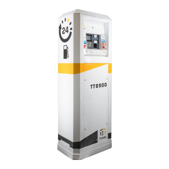
- Page 1 TT8900 Outdoor Payment Terminal Installation and Service Manual October 2021 * TT8900 OPT shown as mounted inside optional supporting cabinet.
- Page 2 Rugged. Purposeful. Effective.
- Page 3 For any questions, technical or otherwise, please contact us: ttfuel.com support@ttfuel.com +61 8 8215 5000 For the latest documentation and product updates, visit our Resource Centre: ttfuel.com/resources...
-
Page 4: Table Of Contents
2.7 Mounting Plinth for the Optional Supporting Cabinet ..............15 2.8 Supporting Cabinet Installation ......................16 2.9 Installing the TT8900 OPT inside the Optional Supporting Cabinet ........16 2.10 TT8900 OPT Cabinet Cable Entry Holes ..................18 2.11 Connecting the Power Supply Unit to the AC Mains Power............. 18 2.12 Connecting the UPS Battery ...................... -
Page 5: Introduction
1.1 Key Information All TT8900 OPT keys are secured registered keys, unique to TT Fuel. In case the OPT has been purchased with its supporting tower, one additional smaller key (per OPT) is supplied for opening the lower access panel. -
Page 6: Tt8900 Opt Specifications
TT8900 OPT – Installation and Service Manual 1.2 TT8900 OPT Specifications EFTPOS / Card Specifications Cards Supported Debit and Credit including Visa / MasterCard / WEX MotorPass / Amex. PIN Pad PCI PTS 5.x with SRED; GBIC, and CCcompliant; EMV Contact L1 & L2 Payment EMV Contactless L1;... - Page 7 TT8900 OPT – Installation and Service Manual Remote Monitoring and Management Internally generated alarms notified to central back-office server for SMS / Email notification. Alarms, amongst others, include: » Emergency Stop activation, mains power failure, UPS battery state. Remote » Low receipt paper, paper out Alarming »...
-
Page 8: Internal Architecture
TT8900 OPT – Installation and Service Manual 1.3 Internal Architecture The TT8900 OPT is based on the next gen TT Fuel proprietary modular T20 Dispensing Control System architecture, ensuring maximum reliability and operational uptime. The T20 DCS comprises of a range of modules that each provide a... -
Page 9: Tandem Configurations
2.13 Forecourt Connections. 1.5 Offline Modes Dealing with authorising electronic payments, the TT8900 OPT default mode of operation is the Online Mode, where all transactions are validated in real time, through its permanent Internet connectivity. However, if Internet connectivity gets disrupted, the TT8900 OPT automatically switches to one of its Offline Modes. -
Page 10: Referenced Documents
TT8900 OPT – Installation and Service Manual 1.6 Referenced Documents TT8900 OPT Installation & Servicing Manual should be read in conjunction with the following referenced documents: Document Title Document Source TT8900 OPT User Manual. TT Fuel T20 Showcase Brochure TT Fuel... -
Page 11: Installation
UPS battery pack and the UPS battery should be disconnected. » The door assembly of the TT8900 OPT weighs approx. 10kg. The oil filled struts that prevent the door from opening too quickly, and restrict its travel, should be inspected regularly to ensure that they are working and are fastened to the door and cabinet securely. -
Page 12: Installation Guidelines
TT8900 OPT – Installation and Service Manual » When the door is open, the corners of the door represent a hazard particularly if someone is working inside in the lower section of the tower enclosure. 2.4 Installation Guidelines It is recommended that the 240VAC supply to the OPT come from a separate circuit that is protected by an RCD. -
Page 13: Available Configurations
There are two available TT8900 OPT configurations, depending on the customer’s existing infrastructure: 1. The TT8900 OPT as a standalone unit, for tank or in-wall mounting or for retrofitting existing supporting cabinets or mounting. TT Fuel supplies this configuration with the TT8900 OPT unit and all the documentation necessary to correctly mount, wire and configure the unit. -
Page 14: Optional Supporting Cabinet
TT8900 OPT – Installation and Service Manual 2.6 Optional Supporting Cabinet The TT8900 OPT can be ordered preinstalled inside a supporting cabinet, designed and engineered to withstand the harsh Australian outback conditions. Figure 1: TT8900 OPT Cabinet Dimensions The supporting cabinet is manufactured from powder-coated 304 grade stainless steel. For maritime environments, there is an option for 316 grade stainless steel to be used. -
Page 15: Mounting Plinth For The Optional Supporting Cabinet
TT8900 OPT – Installation and Service Manual 2.7 Mounting Plinth for the Optional Supporting Cabinet The optional supporting cabinet must be fastened on top of the mounting plinth, designed to support the full supporting cabinet’s weight and provide the required stability. The plinth should be fixed using 4 “dyna-bolts”... -
Page 16: Supporting Cabinet Installation
TT8900 OPT unit will have come up against the bottom shelf of the supporting cabinet. 3. Lifting the front of the TT8900 OPT and sliding it in will allow the hole plugs to clear and the unit to be fully inserted. - Page 17 6. Pull the TT8900 OPT unit towards the front of the supporting cabinet until the mounting bolts prevent it from coming any further forward. 7. While looking at the front of the TT8900 OPT, ensure that the aluminium bezel is sitting square inside the supporting cabinet aperture and that the gap between the bezel and the side faces of the aperture is the same on both sides.
-
Page 18: Tt8900 Opt Cabinet Cable Entry Holes
Figure 5: TT8900 OPT Internal Cabinet Overall Dimensions 2.10 TT8900 OPT Cabinet Cable Entry Holes The TT8900 OPT Internal Cabinet has provision for cable entry via seven holes located in the base of the cabinet. The holes accept a standard plastic or metal 20mm cable gland. -
Page 19: Connecting The Ups Battery
Figure 8: Cellular 2.14 Forecourt Connections Antenna Connection The TT8900 OPT comes standard with support for two PEC/NZ pump communication channels (loops). It can also be optionally fitted with support for one Gilbarco pump communication channel and/or one Email pump communication channel. - Page 20 » Postec FCC interface. » Automatic Tank Gauge (ATG) interface. All standalone or primary TT8900 OPT units are pre-configured from the factory and have the following label (Figure 9) applied on the inside of their enclosure, displaying the connection information...
-
Page 21: Description Of Emergency Stop Interface
TT8900 OPT – Installation and Service Manual Example 1: Having the following external connections will result in a label filled in like the one depicted in Figure 11 - Example 1. » Forecourt Controller (RS232) on channel 1, connectors S41-S43. -
Page 22: Configuration And Testing
TT8900 OPT – Installation and Service Manual 3. Configuration and Testing 3.1 T20 TSM Configuration Unlike the legacy TT8800 OPT, the new TT8900 OPT benefits from a modular approach. As such, all the functionality previously handled by the CAS Card is now managed by the T20 TSM module. -
Page 23: T20 Iim Configuration
TT8900 OPT – Installation and Service Manual 3.2 T20 IIM Configuration The T20 Internal Interface Module (IIM) is used to view the forecourt status and to manage the internal configuration of the TT8900 OPT. Figure 15: TT8900 IIM Module The actual position on the display conveys information about equipment connected to the OPT. -
Page 24: Step By Step Configuration
(6, 14) can be taken either locally or remotely, via a modem/network connection. Figure 17: TT8900 OPT Configuration Steps Note 1: This is a six-digit number that allows both local and remote access to the TT8900 OPT. Note 2: Refer to Part 6 of NMI V 2-1 and NMI V 2-2. - Page 25 TT8900 OPT – Installation and Service Manual Key Action - Description 0 - 9 Selects a menu number or a configuration option. Used to move down through a list. When used in the default screen, it cycles through the configured Tanks information.
- Page 26 DESCRIPTION This is a 6-digit number that allows both local and remote access to the TT8900 OPT. Factory default is 000000. The passcode may be changed 1) PASSCODE if restriction of operator access (to parts of the video monitor menu) is required.
- Page 27 (1 to 32) Enter 0, 1 or 2. This number reflects the channel number that the pump is using. The TT8900 OPT supports two channels (1 and 2). If the status 2) CHANL of a pump is set to 0, the pump is not configured for use and will not appear on the video monitor.
- Page 28 TT8900 OPT – Installation and Service Manual 3) H1-xxx The OTI nozzle tag number that has been assigned to Hose 1. 4) H2-xxx The OTI nozzle tag number that has been assigned to Hose 2. Used to change the display position on the main screen for the selected 5) Position xx pump.
- Page 29 TT8900 OPT – Installation and Service Manual Used to manually enter the meter value for EVERY pump that uses the tank. 6) METER First enter Pump Number then enter pump’s meter reading (up to 9999999). 1) HI ALRM - volume (litres) at which HIGH (overflow) alarm is triggered.
-
Page 30: Commissioning
4.2 Key Handover Every TT8900 OPT comes with two secured registered keys, unique to TT Fuel. In case the OPT has been purchased with its supporting tower, one additional smaller key (per OPT) is supplied for opening the lower access panel. -
Page 31: Servicing
TT8900 OPT – Installation and Service Manual 5. Servicing Having the TT8900 OPT been engineered from the ground up with modularity in mind, its next- gen internal T20 architecture allows most components to be quickly replaced in the field. This chapter covers the printer maintenance and the procedures for replacing the following modules, NOT directly connected, or linked to mains power: »... -
Page 32: Receipt Printer Maintenance
For clearing a paper jam either internally or in the exit slide, follow these steps: 1. Open the TT8900 OPT door using the commissioned key. 2. Gently open the spring-loaded paper guide to check and remove any paper jam in this area. -
Page 33: Replacing The Card Reader
In the unfortunate event the Card Reader needs to be replaced, follow these steps to complete the swap and resume normal operations: 1. Open the TT8900 OPT door using the commissioned key. 2. First power off the UPS battery then, disconnect the TT8900 OPT unit from the mains power. -
Page 34: Replacing The Pin Pad
In the unfortunate event the Pin Pad module needs to be replaced, follow these steps to complete the swap and resume normal operations: 1. Open the TT8900 OPT door using the commissioned key. 2. First power off the UPS battery then, disconnect the TT8900 OPT unit from the mains power. -
Page 35: Replacing The T20 Scm Module
1. Open the TT8900 OPT door using the commissioned key. 2. Power off the UPS battery then, disconnect the TT8900 OPT unit from the mains power. 3. Remove the T20 SCM P1, P2 and P3 connector banks, using a flat head screwdriver. -
Page 36: Replacing The T20 Tsm Module
Setup SW1 dip switches to the old module. 8. Once the front door is closed, turn on the power and resume your TT8900 OPT activity. Figure 25: T20 TSM Module Replacement Note: Make sure to properly align the P1 -P4 connector banks when replacing a T20 TSM module. -
Page 37: Replacing The T20 Iim Module
4. While pushing the module down against the rail, swing the bottom end towards you to release it. 5. Install the new T20 IIM module, undoing steps 3-1. 6. Once the front door is closed, turn on the power and resume your TT8900 OPT activity. Figure 26: T20 IIM Module Replacement Page 37 of 41... -
Page 38: Replacing The Cellular Router
DIN rail until it locks. 6. Undo STEPS 3,2,1. 7. Once the front door is closed, turn on the power and resume your TT8900 OPT activity. Figure 27: T20 CMM Module Replacement Page 38 of 41... -
Page 39: Replacing The Power Supply Unit (Psu)
Figure 28: PSU Replacement as shown in Figure 6. Once the front door is closed, turn on the power and resume your TT8900 OPT activity. 5.9 Replacing the UPS Battery In the unfortunate event the USP battery needs to be replaced, follow these steps to complete the swap and resume normal operations: 1. - Page 40 Disclaimer All endeavours have been made to ensure information contained in this document is correct and accurate at the time of release. TT Fuel does not accept liability for any errors, omissions, or the use of information within this document.
- Page 41 TT Fuel is a global technology business that enables clients to manage the storage and handling of hydrocarbons whilst mitigating risk and realising opportunity. We have global experience supporting companies with fuel management systems, outdoor payment terminals, forecourt controllers, point of sale terminals, bulk fuel loading systems, management software services and specialised fuel storage &...
Need help?
Do you have a question about the TT8900 and is the answer not in the manual?
Questions and answers