Table of Contents
Advertisement
Quick Links
Advertisement
Table of Contents

Related Manuals for BECKWITH ELECTRIC M-4272


Summary of Contents for BECKWITH ELECTRIC M-4272
- Page 1 Instruction Book Book 1 of 2 M-4272 Motor Bus Transfer System...
- Page 2 SYNCHRONIZING Digital Motor Bus Transfer System M-4272 ® Integrated Synchronizing System • Provides Automatic and Manual transfers of motor bus systems in power plants and industrial processing plants to ensure process continuity • Automatically selects Fast, Delayed In-Phase, Residual Voltage, and Fixed Time motor bus transfers, based on varying system conditions •...
- Page 3 M-4272 Digital Motor Bus Transfer System Standard Features Circuit Breaker Control: The digital Motor Bus Transfer System includes the following Circuit Breaker Automatic Transfer: The digital Motor Bus Transfer Control features: System (MBTS) provides the following Automatic • Control of two circuit breakers with two indi-...
- Page 4 M-4272 Digital Motor Bus Transfer System The M-4272 Digital Motor Bus Transfer System provides Automatic and Manual Transfers. The Fast Transfer, Delayed In-Phase Transfer, and Residual Voltage Transfer methods are activated at the same time, if enabled. If the conditions for the Fast Transfer are not met, then the Delayed In-Phase Transfer or the Residual Voltage Transfer will be attempted.
- Page 5 M-4272 Digital Motor Bus Transfer System closes either as a result of a subsequent movement into the delta phase angle limit within the Fast Transfer Time Window, a movement through a predicted zero phase coincidence within the Delayed In-Phase Transfer Time Window, or by a drop in the motor bus voltage below the Residual Voltage Transfer limit, or after the fixed time delay of the Fixed Time Transfer.
- Page 6 M-4272 Digital Motor Bus Transfer System TRANSFER SETTINGS Setpoint † Ranges Increment Accuracy Automatic Transfer Fast Transfer Delta Phase Angle Limit* 0.0 to 90.0 Degrees 0.1 Degree 0.5 Degree Delta Voltage Limit 0 to 60 V 0.5 V or Delta Frequency Limit 0.02 to 2.00 Hz...
- Page 7 M-4272 Digital Motor Bus Transfer System TRANSFER SETTINGS Setpoint Ranges Increment Accuracy † Manual Transfer Fast Transfer Delta Phase Angle Limit* 0.0 to 90.0 Degrees 0.1 Degree 0.5 Degree Delta Voltage Limit 0 to 60 V 0.5 V or Delta Frequency Limit 0.02 to 2.00 Hz...
- Page 8 M-4272 Digital Motor Bus Transfer System TRANSFER SETTINGS Setpoint Ranges Increment Accuracy † Manual Transfer (cont.) Hot Parallel Transfer Delta Phase Angle Limit* 0.0 to 90.0 Degrees 0.1 Degree 0.5 Degree Delta Voltage Limit 0 to 60 V 0.5 V or Delta Frequency Limit 0.02 to 0.50 Hz...
- Page 9 M-4272 Digital Motor Bus Transfer System TRANSFER SETTINGS Setpoint Ranges Increment Accuracy † Common Function Settings Common Function Settings Common Function Settings Common Function Settings Common Function Settings Upper Voltage Limit 5 to 180 V 0.5 V or New Source...
- Page 10 Time Delay 1 to 30 Cycles 1 Cycle 1 Cycle 50BF-1 can be initiated from designated M-4272 output contacts or programmable inputs. * Value in parentheses apply to 1A Secondary Rating 50BF-2 Breaker Failure (Source 2) Pickup Current 0.10 to 10.00 A 0.01 A...
- Page 11 M-4272 Digital Motor Bus Transfer System FUNCTIONS (Cont.) Setpoint Ranges Increment Accuracy † Source 1 Breaker Failure (Using breaker status) Time Delay 0 to 30 Cycles 1 Cycle 1 Cycle The breaker failure time delay is used to monitor breaker failure when using the breaker status inputs only.
- Page 12 M-4272 Digital Motor Bus Transfer System FUNCTIONS (Cont.) Setpoint Ranges Increment Accuracy † Bus VT Fuse-Loss Detection Delta Pickup* 5 to 25 V .05 V or 60FL Time Delay** 1 to 8160 Cycles 1 Cycle 3 Cycles or 1%**** Blocking Drop Out...
- Page 13 When untriggered, the recorder continuously stores waveform data, thereby keeping the most recent data in memory. When triggered, the recorder stores pre-trigger data, then continues to store data in memory for a user- defined, post-trigger delay period. The records may be analyzed using Beckwith Electric ISScom ®...
- Page 14 VA at 120 V. Source voltage may be phase-to ground or phase-to-phase connected. For proper operation of M-4272 MBTS, the connections for the Source 1, Source 2 and Bus voltages must match each other. The unit may have up to three voltage inputs for each of the Source 1, Source 2, and Bus Voltages. Typical connection diagrams are illustrated in Figures 10 through 15.
- Page 15 M-4272 Digital Motor Bus Transfer System Breaker Closing Time and Breaker Failure Monitoring The Breaker Closing Time Monitoring feature measures the breaker closing time each time a transfer occurs. If this time varies by more than a selectable breaker closing time deviation of the programmed time, an alarm is activated.
- Page 16 HMI Module Local access to the M-4272 is provided through the M-3931 Human-Machine Interface (HMI) Module, allowing for easy-to-use, menu-driven access to all functions using a 6-pushbutton keyboard and a 2-line by 24 character alphanumeric display.
- Page 17 M-4272 Digital Motor Bus Transfer System ® Figure 1 ISSLogic Function Diagram –16–...
- Page 18 M-4272 Digital Motor Bus Transfer System Tests and Standards M-4272 Digital Motor Bus Transfer System complies with the following type tests and standards: Voltage Withstand Dielectric Withstand IEC 60255-5 3,500 V dc for 1 minute applied to each independent circuit to earth...
- Page 19 Patent & Warranty The M-4272 Digital Motor Bus Transfer System has patents pending. The M-4272 Digital Motor Bus Transfer System is covered by a five year warranty from date of shipment. External Connections M-4272 external connection points are illustrated in Figure 5, External Connections.
- Page 20 BUS-TIE STATION BUS SYSTEM BUS 1 BUS 2 CT-B1 CT-B2 N.O. THREE-BREAKER CONFIGURATION NOTE: Current Transformers are used for the M-4272, 50BF Function, they are not required for transfer operation. Figure 2 Typical Applications of Motor Bus Transfer Systems –19–...
- Page 21 M-4272 Digital Motor Bus Transfer System Figure 3 Time Sequence of Transfer Logic in Sequential Transfer Mode –20–...
- Page 22 M-4272 Digital Motor Bus Transfer System Figure 4 Time Sequence of Transfer Logic in Simultaneous Transfer Mode –21–...
- Page 23 M-4272 Digital Motor Bus Transfer System –22–...
- Page 24 M-4272 Digital Motor Bus Transfer System Figure 6 Horizontal Mounting Dimensions –23–...
- Page 25 [17.83] 4.00 [10.16] 0.28 [0.71] (4X) RECOMMENDED CUTOUT 4 UNIT PANEL M-4272 TOLERANCE: .XX±.015 Figure 7 Panel Mount Cutout Dimensions BECKWITH ELECTRIC CO., INC. 6190 - 118th Avenue North • Largo, Florida 33773-3724 U.S.A. PHONE (727) 544-2326 • FAX (727) 546-0121 E-MAIL marketing@beckwithelectric.com...
- Page 26 WARNING DANGEROUS VOLTAGES, capable of causing death or serious injury, are present on the external terminals and inside the equip- ment. Use extreme caution and follow all safety rules when han- dling, testing or adjusting the equipment. However, these internal voltage levels are no greater than the voltages applied to the exter- nal terminals.
- Page 27 PRODUCT CAUTIONS Before attempting any test, calibration, or maintenance procedure, personnel must be completely familiar with the particular circuitry of this unit, and have an adequate understanding of field effect devices. If a component is found to be defective, always follow replacement procedures carefully to that assure safety features are maintained.
-
Page 28: Table Of Contents
Instruction Book Chapters Page Chapter 1 Introduction Instruction Book Contents ..............1–1 M-4272 Motor Bus Transfer System ............. 1–2 Application ..................1–4 Chapter 2 Operation Front Panel Controls and Indicators ..........2–1 Alphanumeric Display ................. 2–1 Screen Blanking ................. 2–1 Arrow Pushbuttons ................ - Page 29 M-4272 Instruction Book Chapters - (cont'd) Page Chapter 2 Operation (cont'd) Clear Alarm Counters (MBTS Front Panel) ........2–10 Clear Error Codes (MBTS Front Panel) ........... 2–12 Status Monitoring and Metering ............2–12 System/Monitor/Primary Metering ............2–12 System/Monitor/Secondary Metering and Status ......2–12 System/Monitor/Phasor Diagram and Sync Scope ......
- Page 30 Table of Contents Chapters - (cont'd) Page ® Chapter 3 ISScom (cont'd) System/Sequence of Events/Clear .............3–25 System/Oscillograph ................3–25 System/Oscillograph/Setup ..............3–27 System/Oscillograph/Retrieve ............3–27 System/Oscillograph/Trigger ..............3–28 System/Oscillograph/Clear ..............3–29 System/Profile ..................3–29 System/Profile/Switching Method ............3–29 System/Profile/Active Profile ............. 3–29 System/Profile/Copy Profile ...............3–30 System/Profile/Write File To System ..........
- Page 31 M-4272 Instruction Book Chapters - (cont'd) Page Chapter 4 System Setup and Setpoints (cont'd) HMI Set Date and Time ............... 4–8 Communication Setup ................4–10 Serial Ports (RS-232) ................4–10 Serial Ports (RS-485) ................4–10 Direct Connection ................4–10 Device Address .................. 4–10 ISScom COM Port Definitions and System's Communication Address ..
- Page 32 Table of Contents Chapters - (cont'd) Page Chapter 4 System Setup and Setpoints (cont'd) Common Settings/Auto Fast Transfer Ready Outputs ....4–41 Common Function Settings/Manual Fast Transfer/Hot Parallel Ready Outputs ..............4–41 Common Settings/Transfer Ready Outputs ........4–41 Common Settings/Transfer Completed Outputs ......4–43 Common Settings/Fast Transfer Load Shedding Outputs ....
- Page 33 M-4272 Instruction Book Chapters - (cont'd) Page Chapter 4 System Setup and Setpoints (cont'd) Manual Transfer ................4–55 Manual Transfer Settings/External Control Inputs Configuration ... 4–55 Manual Transfer/Manual Transfer Block ......... 4–55 Manual Transfer/Manual Transfer Initiate ........4–57 Manual Transfer Save/Cancel ............4–57 Manual Transfer Settings/Fast Transfer Tab ........
- Page 34 Table of Contents Chapters - (cont'd) Page Chapter 4 System Setup and Setpoints (cont'd) S1 BF Source 1 Breaker Failure (Breaker Status) ......4–73 S2 BF Source 2 Breaker Failure (Breaker Status) ......4–75 60FL Bus VT Fuse Loss ..............4–75 81 Bus Voltage Frequency ..............
- Page 35 M-4272 Instruction Book Chapters - (cont'd) Page Chapter 6 Testing Power On Self Test ................6–2 Diagnostic Test Procedures .............. 6–3 Overview ....................6–3 Equipment Required ................6–3 Entering Relay Diagnostic Mode ............6–3 Output Relay Test (Output Relays 1–16 and 17) ......... 6–4 Input Test (Control/Status) Inputs 1-18 ..........
- Page 36 1–8 M .............. Order of Possible Open Transition MBTS ........1–10 Chapter 2 M-4272 Front Panel ................2–3 Screen Message Menu Flow ............. 2–3 Main Menu Flow ................. 2–4 Initiate Manual Transfer Confirmation Screen ........2–7 Initiate Manual Transfer Command Sent Confirmation Screen ..2–7 Remote/Local Mode Dialog Screen ...........
- Page 37 M-4272 Instruction Book Figures - (cont'd) Page Chapter 3 (cont'd) 3-11 MBTS Setpoints Dialog Screen ............3–8 3-12 Typical Setpoint Dialog Screen ............3–8 3-13 All Setpoints Table Dialog Screen (Partial) ........3–9 3-14 Configure Dialog Screen (Partial) ............ 3–10 3-15 Date/Time Dialog Screen ..............
- Page 38 Table of Contents Figures - (cont'd) Page Chapter 3 (cont'd) 3-42 Retrieve Oscillograph Record Screen ..........3–28 3-43 Oscillograph Manual Trigger Command Confirmation Screen ..3–28 3-44 Trigger Oscillograph Recorder Command Sent Screen ....3–29 3-45 Clear Oscillograph Records Command Confirmation Screen ..3–29 3-46 Oscillograph Records Cleared Screen ..........
- Page 39 M-4272 Instruction Book Figures - (cont'd) Page Chapter 4 (cont'd) Set Date/Time Dialog Screen ............4–8 System Communication Setup Dialog Screen ........ 4–11 Multiple Systems Addressing Using Communications-Line Splitter ... 4–12 COM Port Settings Warning Screen ..........4–12 4-10 COM Port Setting Verification Screen ..........4–13 4-11 COM Port Settings Sent Confirmation Screen .......
- Page 40 Table of Contents Figures - (cont'd) Page Chapter 4 (cont'd) 4-37 External Status Input Selection Dialog Screen ......4–40 4-38 Common Function Settings Outputs Dialog Screen ....... 4–42 4-39 Auto Fast Transfer Ready Output Selection Dialog Screen ..4–42 4-40 Manual Fast Transfer/Hot Parallel Ready Output Selection Dialog Screen ...................
- Page 41 M-4272 Instruction Book Figures - (cont'd) Page Chapter 4 (cont'd) 4-63 Manual Transfer Settings Hot Parallel Transfer Tab Dialog Screen ............. 4–64 4-64 Hot Parallel Blocking Inputs Selection Dialog Screen ....4–64 4-65 Automatic Trip Settings Dialog Screen ........... 4–66 4-66 Main-Tie-Main Application Example ..........
- Page 42 Single-Phase, Phase-Phase VT Three-Line Connection Diagram .. 5–10 5-10 Single-Phase, Source Side, Phase-Ground, Three-Phase Bus Side, Wye-Wye Three-Line Connection Diagram ........5–11 5-11 Single-Phase, Source Side, Phase-Phase, Three Phase Bus Side, Open Three-Line Connection Diagram ..........5–12 5-12 M-4272 Bottom Circuit Board (B-0970) ........... 5–16...
- Page 43 M-4272 Instruction Book Figures - (cont'd) Page Chapter 5 (cont'd) 5-13 M-4272 B-0957 Top Circuit Board ........... 5–17 5-14 ISScom Program Icon ..............5–18 Chapter 6 Power Supply Connection ..............6–2 MBTS Trip Coil-Close Coil Input Voltage Rating ......6–7 Status LED Panel ................
- Page 44 Table of Contents Tables Page Chapter 1 M-4272 Transfer Functions ..............1–2 M-4272 Device Functions ..............1–2 Chapter 2 Breaker Status LED Input Configurations ......... 2–2 Chapter 3 ISSplot Shortcut Keys ..............3–38 Chapter 4 Dead-Sync Time ................4–11 Recorder Partitions ................4–20 Chapter 5 Jumpers ....................
- Page 45 M-4272 Instruction Book This Page Left Intentionally Blank xviii...
-
Page 46: Chapter 1 Introduction
Introduction – 1 Introduction Instruction Book Contents ............1–1 M-4272 Motor Bus Transfer System (MBTS) ......1–2 Application .................. 1–4 blocking designation. It also illustrates the definition Instruction Book Contents of system quantities and equipment characteristics required by the MBTS, and describes the individual function settings. -
Page 47: M-4272 Motor Bus Transfer System
The M-3931 Human Machine Interface (HMI) Module allows the user to access the following features and Appendix F: Transfer Logic Time Sequence functions from the M-4272 front panel using a menu- driven, 2 line by 24 character alphanumeric display: This Appendix includes the Transfer Logic Time Sequence for each transfer. - Page 48 See Chapter 3, ISScom for a detailed description of Communication Ports all ISScom features. There are three physical communication ports provided on the M-4272. If the optional RJ45 Ethernet M-3972 Status Module port is purchased, then the MBTS shares COM2. The status module (Figure 1-1), includes 24 •...
-
Page 49: Application
The M-4272 MBTS monitors the Source 1 voltage, the Motor Bus voltage and the Source 2 voltage. Figure 1-2 M-3931 Human-Machine The M-4272 also controls the Source 1 and Source Interface (HMI) Module 2 breakers. In a normal transfer a protective MBTS... -
Page 50: Unit-Connected Generator Motor Bus Transfer One-Line
VT-S1 VT-S2 M-4272 VT-B N.C. N.O. STATION BUS SYSTEM NOTE: Current transformers are used for the M-4272 function 50BF, they are not required for transfer operation. Figure 1-3 Typical Two Breaker Configuration TRANSMISSION SYSTEM GENERATOR STEP-UP TRANSFORMER UNIT AUXILIARY STATION SERVICE... - Page 51 N.C. VT-B1 VT-B2 BUS-TIE STATION BUS SYSTEM BUS 1 BUS 2 CT-B1 CT-B2 N.O. NOTE: Current transformers are used for the M-4272 function 50BF, they are not required for transfer operation. Figure 1-5 Industrial Processing Plant Bus transfer One-line 1–6...
-
Page 52: Coastdown Of High Inertia Load On A Large Synchronous Motor
Introduction – 1 Referring to Figures 1-6 and 1-7, a few These parameters are key to analyzing the motor generalizations can be made regarding the inertia of bus transfer issue and developing schemes to motor loads, motor size, and the mix of synchronous accomplish transfers that promote process continuity and induction motors. -
Page 53: V/Hz Resultant Between E And E
M-4272 Instruction Book Hot Parallel, Fast, In-Phase, Residual and The resultant V/Hz issue is exacerbated when the Fixed Time Transfer Methods phase angle difference increases and the voltage difference increases as shown in Figure 1-8. The MBTs can be categorized as closed or open transition following relationship in equation 1 defines this [2]. - Page 54 As the slip frequency breaker does not trip. The M-4272 includes two is changing rapidly due to the deceleration of the Breaker Failure methods (see Section 4.4, System motor bus, calculation of the rate of change of Setpoints).
-
Page 55: Order Of Possible Open Transition Mbts
M-4272 Instruction Book Residual Voltage Transfer phase, residual or fixed time transfer would be initiated. Obviously, the fast transfer offers the In a residual voltage transfer, the motor bus is greatest chance of process continuity, as the connected to the new source after the voltage on interruption period to the motors is short. -
Page 56: Chapter 2 Operation
Indicators decreased by the use of the up and down pushbuttons. This section describes the operation of the M-4272 as a function of the M-3931 Human Machine Interface The up and down arrow pushbuttons increase or Module (HMI) and the M-3972 Status module. -
Page 57: Enter Pushbutton
When a condition exists that causes the operation of SOURCE 1 BREAKER STATUS LEDs Outputs 9 through 16 or Inputs 7 through 18 the RED (CLOSED) assigned Status LED on the M-4272 Front Panel S1 52a Closed S1 52b Open S1 52a and S1 52b will illuminate. -
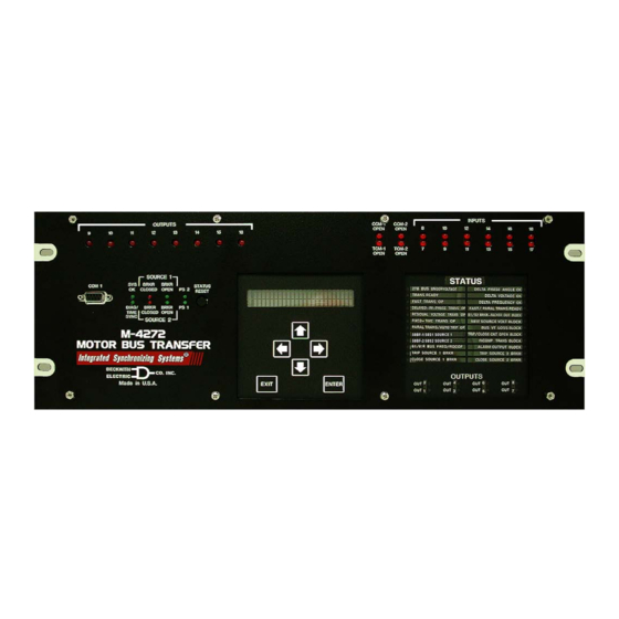
Page 58: M-4272 Front Panel
OUT 2 OUTPUTS OUT 4 OUT 6 OUT 8 OUT 1 OUT 3 OUT 5 OUT 7 Figure 2-1 M-4272 Front Panel Power-On Beckwith Electric Co. Substation Name AUTO FAST TRANSFER Self Tests PICKUP ELEMENTS Default Message Screens POWER ON SELFTESTS... - Page 59 M-4272 Instruction Book INIT TRANSFER DEVICE ON/OFF INIT rmte_lcal ON_OFF exit REMOTE/LOCAL CONTROL EXIT LOCAL MODE init RMTE_LCAL on_off EXIT AUTO TRANSFER AUTO_XFER man_xfer MANUAL TRANSFER auto_xfer MAN_XFER STATUS STAT comm setup Voltage Status • Current Status • Frequency Status •...
-
Page 60: Status Reset Pushbutton
Operation – 2 STATUS RESET Pushbutton angle between the motor bus and the new source is within the delta phase angle limit immediately after Pressing and holding the STATUS RESET the old source breaker opens. pushbutton performs four functions: If the phase angle between the motor bus and the •... -
Page 61: Transfer Methods
M-4272 Instruction Book Transfer Methods Residual Voltage Transfer The type of transfer that occurs when a Manual The conditions that are necessary to execute a Transfer is initiated is determined by the Manual Residual Voltage Transfer are: Transfer settings. Whenever the Hot Parallel Transfer •... -
Page 62: Initiate Manual Transfer (Isscom)
Operation – 2 The MBTS will start the Manual Transfer • The delta frequency between the motor based on the system parameters present bus and the new source is within the limit and MBTS settings. setting. (If this setting is enabled) •... -
Page 63: Remote/Local Control
M-4272 Instruction Book If Level Access is not active, then the HMI will display (scroll) the following following is displayed: screens: MANUAL FAST TRANSFER INIT TRANSFER INIT rmte_lcal 08-NOV-2005 10:11:49.948 MANUAL FAST TRANSFER Verify that the Transfer Ready (Status --OUTPUTS-- Module) indicator is Green. -
Page 64: Remote/Local Control (Mbts Front Panel)
Operation – 2 Select the desired control mode, then Press ENTER. The following will be select Save. displayed: REMOTE/LOCAL CONTROL Verify that the MBTS is in the desired init RMTE_LCAL mode by observing the Remote Mode/ Local Mode status indicator on the Secondary Metering and Status screen The MBTS is now in the selected Control (System Status). -
Page 65: Device On/Off (Mbts Front Panel)
M-4272 Instruction Book Select either Device ON or Device OFF, Press ENTER. The following will be then select Save. displayed: DEVICE ON/OFF Verify that the MBTS is in the desired ON_OFF exit mode by observing the Device On/Off Mode status indicator on the Secondary... - Page 66 Operation – 2 b. If the proper Access Code has been Press ENTER, the following will be entered, the HMI will return: displayed: LEVEL #(1,2 or 3) SOFTWARE VERSION Access Granted! VERS sn access number INIT TRANSFER Press the Right arrow pushbutton until INIT rmte_lcal the following is displayed:...
-
Page 67: Clear Error Codes (Mbts Front Panel)
M-4272 Instruction Book Clear Error Codes (MBTS Front Panel) Press ENTER, the following will be displayed: To clear Error Codes from the Front Panel perform the following: CLEAR ERROR CODES -ERROR CODES CLEARED- Press the ENTER pushbutton. All Error codes have been cleared. -
Page 68: System/Monitor/Phasor Diagram And Sync Scope
Operation – 2 ▲ CAUTION: Do not use the Delta Phase Angle OK, System/Monitor/Phasor Diagram and Sync Scope Delta Voltage OK or Delta Frequency OK status indicators of the ISScom ® software to determine ▲ CAUTION: Do not use the Delta Phase Angle, when to manually initiate a transfer. -
Page 70: Monitor Status/Metering
Operation – 2 Transfer Event Log MBTS Front Panel The initiating event that starts the Transfer Event Monitor Status/Metering Log is the “Start” signal for any transfer. A Transfer The HMI menu categories for monitored values are: Event Log is considered complete when one of •... -
Page 71: Oscillograph
M-4272 Instruction Book Oscillograph The Oscillographic Recorder provides comprehensive data recording of all monitored waveforms, and status inputs storing up to 248 cycles of data. The Oscillographic Recorder is triggered by a designated control/status input (usually a MBTS initiate input), an automatically initiated signal, a trip output, a manual transfer signal or from serial communications. -
Page 72: Chapter 3 Isscom
ISScom – 3 ® ISScom ISScom Functional Description ..........3–1 ISSplot 3–34 ..........................Shortcut Command Buttons This chapter is designed for the person or group responsible for the operation and setup of the MBTS. When the ISScom software opens, there are also 7 The M-3872 ISScom Communications and shortcut command buttons for the most common Oscillographic Analysis Software is required to... - Page 73 M-4272 Instruction Book Help Window Contents File Cascade About... Tile Ctrl+N Open... Ctrl+0 Tools Close System Access Code Comm Access Save Ctrl+S Miscellaneous Setup User Access Save As... System Outputs Test Print Setup System Comm Setup Print Ctrl+P System Ethernet Setup...
-
Page 74: Device On/Off
ISScom – 3 Device ON/OFF Local is defined as originating from the HMI of the MBTS or the RS-232 port COM1 on the front panel. The Device ON/OFF button opens a dialog screen This setting prevents a transfer from being initiated (Figure 3-4), that provides a selection between remotely when personnel are on-site “Locally”... -
Page 75: File Menu
M-4272 Instruction Book File Menu File/Save and Save As Command The Save and Save As... commands allow saving a file or renaming a file, respectively. File/Open Command The open command allows opening a previously created data file. With an opened data file, use the System... - Page 76 ISScom – 3 Figure 3-7 ISScom ® Serial Communication Figure 3-8 ISScom TCP/IP Ethernet Dialog Screen Communication Dialog Screen Figure 3-9 ISScom Modem Expanded Communication Dialog Screen 3–5...
-
Page 77: System Menu
M-4272 Instruction Book System Menu System/Setup/Setup System The Setup System selection displays the Setup System dialog screen (Figure 3-10) allowing the user to input the pertinent information regarding the system on which the MBTS is applied (see Section 4.2, System Setup, for detailed information regarding the specific elements of the Setup System dialog screen). -
Page 78: System/Setup/Setpoints
ISScom – 3 System/Setup/Setpoints DISPLAY ALL JUMP COMMAND BUTTONS The Setpoints menu selection displays the M-4272 This screen includes Jump Command Buttons, that System Setpoints dialog screen (Figure 3-11) from take the user to the corresponding MBTS dialog which the individual Transfer Setting and Function screen or Setup System dialog screen. - Page 79 M-4272 Instruction Book Figure 3-11 MBTS Setpoints Dialog Screen Path: System / Setup / system Setpoints / ATS command button OR ATS jump hotspot within All Setpoints Table Figure 3-12 Typical Setpoint Dialog Screen 3–8...
- Page 80 ISScom – 3 Path: System menu / Setup submenu / Setpoints screen/ Display All button Figure 3-13 All Setpoints Table Dialog Screen (Partial) 3–9...
- Page 81 M-4272 Instruction Book Path: System / Setup submenu / Setpoints screen / Configure button Figure 3-14 Configure Dialog Screen (Partial) 3–10...
-
Page 82: Set Date/Time Command
ISScom – 3 Set Date/Time Command SET DATE AND TIME COMMAND BUTTONS The Set Date/Time command (Figure 3-15) allows Start/Stop This toggles between start/stop, the the system date and time to be set, or system clock Clock MBTS clock. ‘Stop’ pauses, ‘Start’ resumes. -
Page 83: System/Monitor/Primary Metering
M-4272 Instruction Book System/Monitor/Primary Metering The Voltages portion of the metering screen displays the Phase Voltages for the three voltage inputs to The Primary Metering screen (Figure 3-16) allows the MBTS. It also displays the Bus Positive the user to review the Source 1 and Source 2,... - Page 84 ISScom – 3 ▲ CAUTION: Do not use the Delta Phase Angle OK, The Function Status window displays the status of Delta Voltage OK or Delta Frequency OK status various functions, with “T” representing the function indicators of the ISScom ®...
-
Page 85: System/Monitor/Phasor Diagram
Source 2 breaker (CB-S2) is in the open position. allows the user to select/deselect sources to be displayed and Freeze capability to freeze the data In the M-4272 MBT System portion of the screen the displayed on the Phasor Diagram. 52-S1 In-Service and 52-S2 In-Service indicators... - Page 86 ISScom – 3 Path: System / Monitor / Phasor Diagram Figure 3-18 Phasor Diagram Path: System / Monitor / Sync Scope Figure 3-19 Sync Scope Screen 3–15...
-
Page 87: Single Line Diagram (Primary Metering) Or (Secondary Metering) Screen
M-4272 Instruction Book NOTES: If the S1/S2 CT Configuration is set to “No” (S1 & S2 not connected to the rear terminals) (Figure 4-22), then the Single Line Diagram will not display current values. The user may select either the primary or secondary values on the Single Line Diagram. -
Page 88: System/Transfer Event Log
ISScom – 3 System/Transfer Event Log • Open transition time (the time period from when the old source breaker status contact The Transfer Event Log feature captures the following opens to when the new source breaker parameters: status contact closes) •... -
Page 89: System/Transfer Event Log/Download
M-4272 Instruction Book System/Transfer Event Log/Download Select Open. ISScom will display the Open screen with a default “.log” file extension. To download available Transfer Event Logs perform the following: Select the location of the “.log” files, then select the file to be viewed. -
Page 90: Transfer Event Log File Summary Screen
ISScom – 3 Figure 3-23 Transfer Event Log File Summary Screen Figure 3-24 Transfer Event Log File Summary and Details Screen 3–19... -
Page 91: System Status And Transfer Start Signal Status Screen
M-4272 Instruction Book Figure 3-25 System Status and Transfer Start Signal Status Screen 3–20... -
Page 92: System/Transfer Event Log/Clear Status
ISScom – 3 To view the Transfer Event Log Pickup Select YES, ISScom will respond with the Input and Output information, select Pickup Clear Transfer Event Log Status Cleared I/Os. ISScom ® will display the Pickup I/Os confirmation Screen (Figure 3-28). Status screen (Figure 3-26). -
Page 93: System/Sequence Of Events Recorder
M-4272 Instruction Book System/Sequence of Events Recorder The Sequence of Events Recorder submenu allows the user to Setup the events that trigger the Sequence The Sequence of Events Recorder stores every of Events Recorder, Download events from the change in the input status, trip commands, close... -
Page 94: System/Sequence Of Events Recorder/Download
ISScom – 3 System/Sequence of Events Recorder/ Download The Download selection downloads the events from the currently connected MBTS (events must be retrieved from the MBTS and stored in a file in order to view them). To download available Sequence of Events perform the following: ®... -
Page 95: Sequence Of Events File Summary And Details Screen
M-4272 Instruction Book Figure 3-35 Sequence of Events File Summary and Details Screen Select Details. ISScom ® will expand the Sequence of Events Viewer screen to include the Details section (Figure 3-35) which includes additional Sequence of Events information. To print the Sequence of Events Summary information select Print Summary. -
Page 96: System/Sequence Of Events/Clear
ISScom – 3 To view the Sequence of Events Dropout Select YES, ISScom will respond with the Input and Output information select Dropout Sequence of Events Records Cleared I/Os. ISScom ® will display the Dropout I/Os confirmation Screen (Figure 3-40). Status screen (Figure 3-37). - Page 97 M-4272 Instruction Book Figure 3-38 Sequence of Events System Status and Transfer Start Signal Status Screen 3–26...
-
Page 98: System/Oscillograph/Setup
ISScom – 3 The following parameters are captured by the • Delta frequency Oscillographic Recorder: • Trip Circuit Monitor (TCM) or Close Circuit Monitor (CCM) open signal. • MBTS start (initiate) signal. It can be • Inputs 1—18 manual transfer initiate, protective relay initiate, or bus phase undervoltage initiate. -
Page 99: System/Oscillograph/Trigger
M-4272 Instruction Book To Retrieve Oscillograph recorders perform the To manually Trigger the Oscillograph Recorder following: perform the following: ® From the ISScom Main Screen menu select From the ISScom Main Screen menu select System/Oscillograph/Retrieve. ISScom will System/Oscillograph/Trigger. ISScom will... -
Page 100: System/Oscillograph/Clear
ISScom – 3 System/Profile The system supports four setpoint profiles. This feature allows multiple setpoint profiles to be defined for the type of transfer initiated (Automatic, Manual or Hot Parallel) and the direction of the next transfer. The Profile submenu provides three selections: Switching Method, Active Profile, and Copy Profile. -
Page 101: System/Profile/Copy Profile
M-4272 Instruction Book Browse to the location of the file to be written to the MBTS, then select the target file. Select OPEN, ISScom will write the file contents to the target MBTS. When the file has been successfully written to the MBTS... -
Page 102: Tools Menu
ISScom – 3 Tools Menu The MBTS includes three levels of access codes. Depending on their assigned code, users have varying levels of access to the installed functions. Level 1 Access = Read setpoints, monitor status, view status history. Level 2 Access = All of level 1 privileges, plus read &... -
Page 103: Tools/System Outputs Test
M-4272 Instruction Book User Control Number Tools/System Outputs Test The User Control Number is a user-defined value The System Outputs Test menu selection displays which can be used for inventory or identification. the System Outputs Test screen (Figure 3-55) which... -
Page 104: Tools/System Comm Setup
The System Firmware Update selection allows the user to update MBTS firmware version in the field. Detailed step by step instructions will be provided by Beckwith Electric regarding Field Firmware Updates. Tools/Calibrate Unit The Calibrate Unit menu selection provides the... -
Page 105: Issplot
M-4272 Instruction Book ISSplot ISSplot allows the user to plot and print waveform data downloaded from Beckwith Electric MBTSs. The ISSplot feature is also capable of plotting and printing waveform data files that are in COMTRADE format. When the ISSplot menu item is selected, ISSplot is launched in an independent Windows Window. - Page 106 ISScom – 3 ISSplot PLUS Window Help File View Settings Help Window Contents Cascade File About ISSplot Arrange Icons (Windows File Path) Settings View Figure 3-60 ISSplot Menu Structure and Submenu Callouts 3–35...
-
Page 107: Issplot File Menu
M-4272 Instruction Book ISSplot File Menu ISSplot Select Waveforms The ISSplot File menu allows the user to open an Allows the selection of voltages, currents, inputs, ® oscillograph file previously downloaded by ISScom and outputs to be plotted or printed. - Page 108 ISScom – 3 NOTE: Cursor bars may be dragged to any location by positioning the cursor arrow on a bar and dragging the mouse. Double click the left key to position one cursor bar and Shift-Double Click or left mouse down and click the right key to position the other cursor bar at the current cursor arrow time position.
-
Page 109: Issplot Window Menu/Help Menu
M-4272 Instruction Book ISSplot Change Scale ISSplot Window Menu/Help Menu Allows the individual designation of a magnitude Window scale for voltage and current traces. ISSplot Default Sets all similar waveforms to the same scale (largest). ISSplot Auto All Allows ISSplot to set the scale for each individual The Window menu enables the positioning and waveform. - Page 110 ISScom – 3 Move Zoom In View All Delta Phase Delta Waveform Left Phase Diagram Frequency Move Open Print Move to the Zoom Out Angle Right Original Beginning Waveform Move to the Fundamental Rate of Change Waveform of Bus Frequency Figure 3-65 ISSplot Toolbar MARKER #2...
-
Page 111: Window Menu/Help Menu
Document File) version of this instruction book for easy reference. An Adobe Acrobat ® reader is required to view this document. The M-4272 Instruction Book Figure 3-67 About ISScom Dialog Box has been Bookmarked. By selecting the “Navigator pane’ in Adobe Acrobat Reader, the user can directly access selected topics. -
Page 112: Chapter 4 System Setup And Setpoints
Chapter four is designed for the person or group 4.1 Unit Setup responsible for the Unit Setup, System Setup and System Setpoints of the M-4272 Digital Motor Bus Transfer System (MBTS). NOTE: Setup Record Forms are contained in Appendix A. The Setup Record Form... -
Page 113: Isscom Access Code Setup
M-4272 Instruction Book ® ISScom Comm Access Code Setup HMI Comm Access Code Setup Press the ENTER pushbutton. To set the MBTS Comm Access Code perform the following: If Level Access is active, the following is displayed: NOTE: Communication must be established with the target MBTS for this procedure. -
Page 114: Isscom User Access Codes Setup
System Setup and Setpoints – 4 Input the desired Comm Access Code ® ISScom User Access Codes Setup as follows: To set the MBTS User Access Codes perform the following: Utilizing the Up and Down arrow pushbuttons select the desired first NOTE: Communication must be established with digit. -
Page 115: Hmi User Access Codes Setup
M-4272 Instruction Book Input the desired User Access Code as HMI User Access Codes Setup follows: Press the ENTER pushbutton. Utilizing the Up and Down arrow If Level Access is active, the following pushbuttons select the desired first is displayed: digit. -
Page 116: User Logo Line
System Setup and Setpoints – 4 If enabling/disabling the System OK LED USER LOGO LINE Flash operation, then select either Enable The user logo is a programmable, two-line by of Disable. 24-character string, which can be used to identify Select OK, ISScom will return to the the MBTS, and which is displayed locally when the Main Screen. -
Page 117: Hmi User Control Number Setup
M-4272 Instruction Book Press ENTER, the following will be When the desired User Logo Line 2 has displayed: been input, then press ENTER. The following will be displayed: USER LOGO LINE 1 _BECKWITH ELECTRIC CO. USER LOGO LINE 2 —WAIT—... -
Page 118: Hmi System Ok Led Setup
System Setup and Setpoints – 4 Press the Right arrow pushbutton until If Level Access is not active, then the the following is displayed: following is displayed: INIT TRANSFER USER CONTROL NUMBER INIT rmte_lcal vers sn access NUMBER ▲ ▲ ▲ ▲ ▲ CAUTION: Do not enter DIAGNOSTIC MODE Press ENTER, the following will be displayed: when protected equipment is in service. -
Page 119: System Clock
M-4272 Instruction Book Press ENTER, the following will be ISScom Set Date/Time displayed: To set the MBTS Date/Time perform the following: FLASH SYS OK LED NOTE: Communication must be established with the target MBTS for this procedure. Utilizing the Right or Left arrow From the ISScom Main Screen menu pushbuttons select either ON or OFF. - Page 120 System Setup and Setpoints – 4 If Level Access is not active, then the When the desired Month has been following is displayed: selected, then press ENTER. The following will be displayed: INIT TRANSFER INIT rmte_lcal DATE & TIME 8 Date Press the RIGHT arrow pushbutton until the following is displayed: Input the desired Date as follows:...
-
Page 121: Communication Setup
Other communication topologies are possible using • COM Port definitions and Device Address the M-4272 Digital Motor Bus Transfer System. An • Ethernet Port Settings Application Note, “ Serial Communication with Beckwith Electric’s Integrated Protection System • Installing Modems Relays ”... -
Page 122: Isscom Com Port Definitions And System's Communication Address
System Setup and Setpoints – 4 ISScom COM Port Definitions and System’s Communication Address To setup the COM Ports and Communication Baud Rate Dead-Sync Time Addresses perform the following: 9600 4 ms NOTE: Communication must be established with the target MBTS for this procedure. 4800 8 ms From the ISScom... - Page 123 M-4272 Instruction Book Enter desired “System’s When the COM Port settings have been Communication Address” (1 to 255). entered, then select Save. ISScom will display the COM Port Settings Warning The individual addressing capability of Screen (Figure 4-9). ® ISScom...
-
Page 124: Hmi Com Port Definitions And Device Addresses
System Setup and Setpoints – 4 INIT TRANSFER Select Yes, ISScom ® will display the INIT rmte_lcal COM Port Setting Verification screen (Figure 4-10). Go to step 4. If Level Access is not active, then the following is displayed: INIT TRANSFER INIT rmte_lcal Press the Right arrow pushbutton until... -
Page 125: Ethernet Communication Settings
M-4272 Instruction Book Press the Left or Right arrow pushbutton ISScom Ethernet Port Setup with DHCP as necessary to select the desired Parity NOTE: Communication must be established with setting. the target MBTS for this procedure. Press ENTER, the following will be... -
Page 126: Hmi Ethernet Port Setup
System Setup and Setpoints – 4 Use the Right arrow pushbutton to select HMI Ethernet Port Setup ENABLE (Upper Case), then press Press the ENTER pushbutton. ENTER, the following will be displayed: If Level Access is active, the following is displayed: TCP/IP SETTINGS TCP_SETTINGS ENTER ACCESS CODE... -
Page 127: Hmi Manual Configuration Of Ethernet Board
M-4272 Instruction Book If the ethernet board fails to obtain an IP Use the Right arrow pushbutton to select Address within 15 seconds the following ETH (Upper Case). will be displayed (for approximately 2 ETHERNET SETUP seconds): access eth_ip CONFIGURING ETH... -
Page 128: Installing The Modems
System Setup and Setpoints – 4 Press EXIT, the ethernet board will Verify that the modem is attached to (if reconfigure and the following will be external) or assigned to (if internal) the displayed: same serial port as assigned in ISScom. While ISScom can use any of the 255 CONFIGURING ETH... -
Page 129: Connecting The Local Modem To The Mbts
M-4272 Instruction Book Open TCP_IP Initiates contact with the protective Connecting the Local Modem to the MBTS system by ethernet connection. Setup of the modem attached to the MBTS may be slightly complicated. It involves programming Close TCP_IP Closes Ethernet Connection parameters (using the AT command set), and storing this profile in the modem’s nonvolatile memory. -
Page 130: Oscillograph Setup
System Setup and Setpoints – 4 There are some variations in the AT commands supported by modem manufacturers. Refer to the hardware user documentation for a list of supported AT commands and direction on issuing these commands. OSCILLOGRAPH SETUP The oscillographic recorder provides comprehensive data recording of all monitored waveforms, and status inputs storing up to 248 cycles of data. - Page 131 M-4272 Instruction Book NOTE: Table 4-2 is based on 32 samples per programmed portion of the total record second. For other sample rates the before re-arming for the next record. For number of cycles per partition has to be example, a setting of 80% will result in a scaled accordingly.
- Page 132 System Setup and Setpoints – 4 Figure 4-16 Setup Oscillograph Recorder Figure 4-17 Oscillograph Setup Sent Confirmation Screen 4–21...
-
Page 133: Sequence Events Recorder Setup
M-4272 Instruction Book Select the desired Inputs and Outputs, SEQUENCE OF EVENTS RECORDER SETUP then select Save. ISScom will display a Protective function Pickup, Trip, Dropout and/or Send Changes to Unit Screen Output/Input Pickup or Dropout are selected to (Figure 4-19). -
Page 134: System Setup
System Setup and Setpoints – 4 Enter the Nominal Current. The System Setup secondary CT current of the phase CTS. Select the Phase Rotation. (ABC or NOTE: Setup Record Forms are contained in ACB). Appendix A. The Setup Record Form NOTE: See Section 4.3, System Diagrams for tables list the MBTS parameter settings Typical VT Three-Line Connection... - Page 135 M-4272 Instruction Book Figure 4-20 Setup System Dialog Screen Figure 4-21 S1/S2 VT Configuration Selection Screen 4–24...
- Page 136 System Setup and Setpoints – 4 Select the S1/S2 CT Configuration Select the desired outputs to be Latched, button. ISScom displays the S1/S2 CT then select OK, ISScom will return to Configuration Selection screen (Figure the Setup System screen. 4-22). The S1/S2 CT Confguration NOTE: If neither pulsed or latched output is Selection is based on whether the S1 and enabled, then the output contact will default...
- Page 137 This fully racked-in. If the breaker is not fully setting is only used if the output has not racked-in (in test position), the M-4272 been selected as a latched output. The will block any type of transfer.
- Page 138 System Setup and Setpoints – 4 NOTE: If neither pulsed or latched output is enabled, then the output contact will default to the Normal Mode. Normal Mode maintains the output contact energized as long as the condition that caused it to operate exists.
-
Page 139: System Diagrams
M-4272 Instruction Book System Diagrams SOURCE 1 (S1) SOURCE 2 (S2) CT-S2 Single Phase CT CT-S1 Single Phase CT M-4272 M-4272 VT-S1 Three VT Wye-Wye Connection VT-S2 Three VT Wye-Wye Connection M-4272 M-4272 VT-B Three VT Wye-Wye Connection M-4272 52S1... - Page 140 System Setup and Setpoints – 4 SOURCE 1 (S1) SOURCE 2 (S2) CT-S2 Single Phase CT CT-S1 Single Phase CT M-4272 M-4272 VT-S1 Two VT Open-Delta Connection VT-S2 Two VT Open-Delta Connection M-4272 M-4272 VT-B Two VT Open-Delta Connection M-4272...
- Page 141 M-4272 Instruction Book SOURCE S1 (S1) SOURCE 2 (S2) CT-S1 Single Phase CT CT-S2 Single Phase CT M-4272 M-4272 VT-S1 One VT VT-S2 One VT Phase-Ground Phase-Ground Connection Connection M-4272 M-4272 VT-B One VT Phase-Ground Connection M-4272 52S1 52S2 STATION BUS SYSTEM...
- Page 142 System Setup and Setpoints – 4 SOURCE 1 (S1) SOURCE 2 (S2) CT-S1 Single Phase CT CT-S2 Single Phase CT M-4272 M-4272 VT-S1 One VT VT-S2 One VT Phase-Phase Phase-Phase Connection Connection M-4272 M-4272 VT-B One VT Phase-Phase Connection M-4272...
- Page 143 M-4272 Instruction Book SOURCE 1 (S1) SOURCE 2 (S2) CT-S1 Single Phase CT CT-S2 Single Phase CT M-4272 M-4272 VT-S1 One VT VT-S2 One VT Phase-Ground Phase-Ground Connection Connection M-4272 M-4272 VT-B Three VT Wye-Wye Connection M-4272 52S1 52S2 STATION BUS SYSTEM...
- Page 144 System Setup and Setpoints – 4 SOURCE 1 (S1) SOURCE 2(S2) CT-S1 Single Phase CT CT-M2 Single Phase CT M-4272 M-4272 VT-S1 One VT VT-S2 One VT Phase-Phase Phase-Phase Connection Connection M-4272 M-4272 VT-B Two VT Open-Delta Connection M-4272 52S1...
-
Page 145: System Setpoints
System Setpoints can only be entered using the is performed. Therefore, the settings in the Common M-3872 software. See Section 1.2, M-4272 Motor Settings submenu must be entered for a transfer to Bus Transfer System for a listing of those Settings, operate correctly. -
Page 146: Transfer Settings
System Setup and Setpoints – 4 TRANSFER SETTINGS COMMON SETTINGS (CS) Path: System/Setup/Setpoints/Common Settings The Common Settings selection from the Transfer Settings group (Figure 4-33) opens the Common Function Settings Dialog screen (Figure 4-34), which includes the Common Function Settings, Inputs and Outputs tabs. -
Page 147: Common Settings/Common Function Settings Tab
M-4272 Instruction Book of the new source breaker without waiting COMMON SETTINGS/COMMON FUNCTION for the breaker status contact confirmation SETTINGS TAB that the old source breaker has opened. Path: System/Setup/Setpoints/Common Settings At the same instant, the commands for Figure 4-34, illustrates the MBTS Common Function... -
Page 148: Common Settings/Upper-Lower Voltage Limit New Source
System Setup and Setpoints – 4 • Sequential — With a transfer initiated, eight breaker operations have been averaged. the command to trip the old source breaker Breaker Closing Time setpoints cannot be changed is sent within 10 ms. Upon confirmation while this feature is enabled. -
Page 149: Common Settings/Local Manual Initiate Time Delay
This Common Settings Save/Cancel — The Save assumes that the M-4272 is physically located on selection (Figure 4-34) saves the Common Function the switchgear. Typically, manual transfers occur... -
Page 150: Common Function Settings Inputs Tab
During commissioning, when a bus user with the ability to select the type of 52 breaker transfer test is simulated, the M-4272 needs to see status contact being used for Source 1 and Source the 52a and 52b contacts change state even when 2. -
Page 151: Common Settings/External Control Inputs Configuration
M-4272 Instruction Book Common Settings/External Control Inputs Common Settings/External Status Reset Configuration This feature allows the user to select the external input to be used to reset the system status and any The External Control Inputs Configuration section selected latched outputs. When the External Status... -
Page 152: Common Settings Outputs Tab
System Setup and Setpoints – 4 • The Delta Voltage between the Motor Bus COMMON SETTINGS OUTPUTS TAB and the New Source is within limit setting. Path: System/Setup/Setpoints/Common Settings/ • The Delta Frequency between the Motor Outputs Bus and the New Source is within limit Figure 4-38, illustrates the MBTS Common Function setting. - Page 153 M-4272 Instruction Book Figure 4-38 Common Function Settings Outputs Dialog Screen Figure 4-39 Auto Fast Transfer Ready Output Figure 4-40 Manual Fast Transfer/Hot Selection Dialog Screen Parallel Ready Output Selection Dialog Screen 4–42...
-
Page 154: Common Settings/Transfer Completed Outputs
System Setup and Setpoints – 4 The Transfer ready indication only indicates that • Blocking After Transfer — After a transfer there are no blocking conditions, it does not indicate has been completed, any additional the Delta Phase Angle, Delta Frequency, or Delta transfers are blocked for 0 to 8160 cycles, Voltage parameters are within the settings of the as selected by the user. -
Page 155: Common Settings/Load Shedding Outputs
M-4272 Instruction Book The Delayed In-Phase Transfer Load Shedding For the F27B 3, F81 1 or F81R 1 functions, when command is sent at the end of the Fast Transfer the settings are satisfied the selected load shedding time window if a fast transfer has not been completed. - Page 156 System Setup and Setpoints – 4 Figure 4-44 Delayed In-Phase Transfer Load Figure 4-45 Incomplete Transfer Outputs Shedding Output Selection Dialog Screen Selection Dialog Screen Figure 4-46 Load Shedding Output Selection Dialog Screen 4–45...
-
Page 157: Automatic Transfer Settings (Ats)
Block Transfer is selected, then no transfer is performed Input the required Access Code, then by the M-4272. While this condition continues to press ENTER. exist any transfer initiated externally or internally will If the proper Access Code has been be blocked and no transfers will occur. - Page 158 System Setup and Setpoints – 4 the Automatic Transfer feature. The transfer method AUTOMATIC TRANSFER SETTINGS SETUP used will depend on how the motor bus voltage TAB/EXTERNAL CONTROL INPUTS decays when the power source is disconnected. CONFIGURATION For example, assume the Source 1 breaker is Path: System/Setup/Setpoints/Automatic Transfer closed and the Source 2 breaker is open.
- Page 159 M-4272 Instruction Book The selected input will initiate an Automatic Transfer Automatic Transfer/Auto Transfer Block from Source 2 to Source 1. If the Source 1 breaker The Auto Transfer Block selection opens the Auto is closed and the Source 2 breaker is open the...
-
Page 160: Automatic Transfer Settings Fast Transfer Tab
System Setup and Setpoints – 4 AUTOMATIC TRANSFER SETTINGS FAST Automatic Fast Transfer/Delta Phase Angle TRANSFER TAB Limit The Delta Phase Angle Limit (Figure 4-49) can be set Path: System/Setup/Setpoints/Automatic Transfer from 0.0 to 90.0 degrees. The Delta Phase Angle is Settings/Fast Transfer the angle between the voltages of the motor bus and The Fast Transfer tab (Figure 4-49) displays the... -
Page 161: Fast Transfer Tab Save/Cancel
M-4272 Instruction Book Automatic Fast Transfer/Time Window Automatic Fast Transfer/Blocking Inputs Selection The Time Window (Figure 4-49) can be set from 1 to 10 cycles. The Time Window defines the window of The Blocking Inputs Selection button (Figure 4-49) opportunity for a Fast Transfer. The Time Window... -
Page 162: Automatic Transfer Settings/Delayed In-Phase Transfer Tab
System Setup and Setpoints – 4 AUTOMATIC TRANSFER SETTINGS/DELAYED Automatic Delayed In-Phase Transfer/Delta IN-PHASE TRANSFER TAB Voltage Limit The Delta Voltage Limit can be set from 0 to120 volts. Path: System/Setup/Setpoints/Automatic Transfer The Delta Voltage is the voltage difference between Settings/Delayed In-Phase Transfer the motor bus and the new source. -
Page 163: Automatic Transfer Settings/Residual Voltage Transfer Tab
M-4272 Instruction Book • The Delta Frequency between the motor Automatic Delayed In-Phase Transfer/Blocking bus and the new source is within limit Inputs Selection setting. The Blocking Inputs Selection button opens the Blocking Inputs Selection dialog screen (Figure • The Phase Angle between the motor bus 4-50). -
Page 164: Automatic Transfer Settings/Fixed Time Transfer Tab
System Setup and Setpoints – 4 The Residual Voltage Transfer tab (Figure 4-52) Automatic Residual Voltage Transfer Save/ displays the settings for the Residual Voltage Cancel Transfer. The top right corner of the display includes The Save selection saves the Automatic Residual a command button that will disable or enable the Voltage Transfer Tab settings either to an open file automatic Residual Voltage Transfer. -
Page 165: Auto Fixed Time Transfer/Time Delay
M-4272 Instruction Book Automatic Fixed Time Transfer/Time Delay Automatic Fixed Time Transfer/Blocking Inputs Selection The Time Delay setting can be set from 30 to 1000 cycles. When the conditions are met for a Fixed Time The Blocking Inputs Selection button opens the Blocking Transfer the Time Delay starts timing. -
Page 166: Manual Transfer Settings (Mts)
System Setup and Setpoints – 4 Press ENTER, the following will be MANUAL TRANSFER SETTINGS displayed: (MTS) MANUAL TRANSFER disable enable Path: System/Setup/Setpoints/Manual Transfer Settings The Manual Transfer Settings selection from the Transfer Settings group (Figure 4-33) opens the Press the Left or Right arrow pushbutton Manual Transfer Settings Dialog screen (Figure as necessary to enable or disable Manual 4-54), which includes the following tabs:... - Page 167 M-4272 Instruction Book Figure 4-54 Manual Transfer Settings Dialog Screen Figure 4-55 Manual Block Input Settings Figure 4-56 Manual Transfer Initiate Input Dialog Screen Settings Dialog Screen 4–56...
-
Page 168: Manual Transfer/Manual Transfer Initiate
System Setup and Setpoints – 4 angle is always one of the parameters used to Manual Transfer/Manual Transfer Initiate determine if a fast transfer can be executed. The Manual Transfer Initiate opens a dialog screen (Figure 4-56) that allows the user to select an input Manual Fast Transfer/Delta Voltage Limit or inputs that are used to initiate Manual Transfers. - Page 169 M-4272 Instruction Book Figure 4-57 Manual Transfer Settings Fast Transfer Tab Dialog Screen Figure 4-58 Manual Fast Transfer Blocking Inputs Selection Dialog Screen 4–58...
-
Page 170: Manual Transfer Settings/Delayed In-Phase Transfer Tab
System Setup and Setpoints – 4 The Conditions that are necessary to execute a This setting cannot be disabled. The frequency is Manual Fast Transfer are: always one of the parameters used to determine if a Delayed In-Phase Transfer can be executed. •... - Page 171 M-4272 Instruction Book Figure 4-59 Manual Transfer Settings Delayed In-Phase Transfer Tab Dialog Screen Figure 4-60 Delayed In-Phase Transfer Blocking Inputs Selection Dialog Screen 4–60...
-
Page 172: Manual Transfer Settings/Residual Voltage Transfer Tab
System Setup and Setpoints – 4 MANUAL TRANSFER SETTINGS/RESIDUAL Manual Residual Voltage Transfer/Load VOLTAGE TRANSFER TAB Shedding Time Delay The Load Shedding Time Delay can be set from 2 to Path: System/Setup/Setpoints/Manual Transfer 100 cycles. The time delay defines the time period Settings/Residual Voltage Transfer from when the motor bus voltage decreases to less The Residual Voltage Transfer tab (Figure 4-61) - Page 173 M-4272 Instruction Book Figure 4-61 Manual Transfer Settings Residual Voltage Transfer Tab Dialog Screen Figure 4-62 Residual Voltage Transfer Blocking Inputs Selection Dialog Screen 4–62...
-
Page 174: Manual Transfer Settings/Hot Parallel Transfer Tab
System Setup and Setpoints – 4 MANUAL TRANSFER SETTINGS/HOT Manual Hot Parallel Transfer/Time Window PARALLEL TRANSFER TAB The Time Window can be set from 1 to 50 cycles. The Time Window defines the window of opportunity Path: System/Setup/Setpoints/Manual Transfer for a Hot Parallel Transfer. The Time Window starts Settings/Hot Parallel Transfer when the transfer is initiated and ends at the selected The Hot Parallel Transfer tab (Figure 4-63) displays... - Page 175 M-4272 Instruction Book Figure 4-63 Manual Transfer Settings Hot Parallel Transfer Tab Dialog Screen Figure 4-64 Hot Parallel Blocking Inputs Selection Dialog Screen 4–64...
-
Page 176: Auto Trip (At)
System Setup and Setpoints – 4 AUTO TRIP (AT) Auto Trip/Enable/Disable In the top right corner of the screen is a command Path: System/Setup/Setpoints/Auto Trip button that will Disable or Enable the Auto Trip feature. The Auto Trip selection from the Transfer Settings group (Figure 4-33) opens the Auto Trip Dialog Auto Trip/Breaker Trip Option screen (Figure 4-65). - Page 177 M-4272 Instruction Book Figure 4-65 Automatic Trip Settings Dialog Screen NORMAL SOURCE #1 NORMAL SOURCE #2 NORMAL SOURCE #1 NORMAL SOURCE #2 TRANSFORMER TRANSFORMER CT-M1 CT-M2 M-4272 M-4272 VT-M1 VT-M2 N.C. N.C. VT-B1 VT-B2 BUS-TIE STATION BUS SYSTEM BUS 1...
-
Page 178: Function Settings
System Setup and Setpoints – 4 be disabled (or enabled) independent from the 27#2 FUNCTION SETTINGS Bus Phase Undervoltage Transfer Initiate (S2 to S1), 27#3 Bus Phase Undervoltage or the 27#4 Bus Phase Undervoltage. Path: System/Setup/Setpoints The Function Settings Group (Figure 4-33) includes Pickup —... - Page 179 M-4272 Instruction Book Figure 4-67 Function Settings Bus Phase Undervoltage Transfer Initiate (S1 to S2) Dialog Screen Figure 4-68 27B#1 Bus Phase Undervoltage Transfer Initiate Inputs/Outputs Selection Dialog Screen 4–68...
-
Page 180: Source 1 Instantaneous Phase Overload Detection
System Setup and Setpoints – 4 pickup for normal load current conditions. Ranges 50 SOURCE 1 INSTANTANEOUS and Increments are presented in Figure 4-70. Since PHASE OVERLOAD DETECTION this is only a single phase element, the 50S1 Function can only be used for overload detection Path: System/Setup/Setpoints/50S1 and not used for overcurrent protection. -
Page 181: Source 2 Instantaneous Phase Overload Detection
M-4272 Instruction Book pickup for normal load current conditions. Ranges 50 SOURCE 2 INSTANTANEOUS and Increments are presented in Figure 4-71. Since PHASE OVERLOAD DETECTION this is only a single phase element the 50S2 Function can only be used for overload detection... -
Page 182: 50Bf #1 Source 1 Breaker Failure
System Setup and Setpoints – 4 status would indicate that the tripped breaker did 50BF #1 SOURCE 1 BREAKER not open. Since the transfer could not be completed FAILURE the Incomplete Transfer Lockout timer would time out and generate a lockout condition. Path: System/Setup/Setpoints/50BF#1 Time Delay —... - Page 183 M-4272 Instruction Book Figure 4-74 50BF #1 Source 1 Breaker Failure I/O Selection Dialog Screen Figure 4-75 50BF #1 Source 1 Breaker Failure Initiate Inputs/Initiate Outputs Selection Dialog Screen 4–72...
-
Page 184: 50Bf #2 Source 2 Breaker Failure
System Setup and Setpoints – 4 tripped, the breaker that was just closed will be 50BF #2 SOURCE 2 BREAKER tripped. This prevents the New Source from FAILURE continuing to be connected through the failed breaker to the old source that may be faulted. Path: System/Setup/Setpoints/50BF#2 If the Sequential Transfer mode is selected... - Page 185 M-4272 Instruction Book Figure 4-77 S1 BF Source 1 Breaker Failure (Breaker Status) Dialog Screen Figure 4-78 S1 BF Source 1 Breaker Failure (Breaker Status) I/O Selection Dialog Screen 4–74...
-
Page 186: S2 Bf Source 2 Breaker Failure (Breaker Status)
System Setup and Setpoints – 4 Three-Phase connection) or the Single Phase voltage S2 BF SOURCE 2 BREAKER FAILURE of the motor bus to the Single Phase voltages of the (BREAKER STATUS) connected source (VT’s in single phase connection): Path: System/Setup/Setpoints/S2 BF •... - Page 187 M-4272 Instruction Book Figure 4-80 60FL Bus VT Fuse Loss Dialog Screen Figure 4-81 60FL Bus VT Fuse-Loss Function Inputs/Outputs Selection Dialog Screen 4–76...
-
Page 188: 81 Bus Voltage Frequency
System Setup and Setpoints – 4 81 BUS VOLTAGE FREQUENCY Path: System/Setup/Setpoints/81 Time Delay — A Time Delay (5 to 65500 cycles) Figure 4-82 displays the settings for the 81 #1 Bus can be applied to delay the Bus Voltage Frequency Voltage Frequency function. - Page 189 M-4272 Instruction Book Figure 4-82 81 #1(2) Bus Voltage Frequency Function Dialog Screen Figure 4-83 81 #1(2) Bus Voltage Frequency Function Inputs/Outputs Selection Dialog Screen 4–78...
-
Page 190: Rocof (Bus Voltage)
System Setup and Setpoints – 4 Time Delay — A Time Delay can be applied to 81R (Rate Of Change Of Frequency) delay the 81R ROCOF (Bus Voltage) function output. (BUS VOLTAGE) The time delay and magnitude settings of the 81R should be based on simulation studies. - Page 191 M-4272 Instruction Book Figure 4-84 81R #1(2) ROCOF (Bus Voltage) Function Dialog Screen Figure 4-85 81R #1(2) ROCOF (Bus Voltage) Inputs/Outputs Selection Dialog Screen 4–80...
-
Page 192: Ccm (Close Circuit Monitor)
2 mA. • An open condition has been detected in ▲ ▲ ▲ ▲ ▲ CAUTION: Connecting the M-4272 Close Coil the close coil circuit for the duration of the Monitor (CCM) in parallel with other relay CCMs in Time Delay. - Page 193 M-4272 Instruction Book I/O Selection — The I/O Selection button opens Save/Cancel — The Save selection saves the CCM (Close Circuit Monitor) I/O Selection Dialog CCM (Close Circuit Monitor) Function Dialog Screen Screen (Figure 4-88) that allows any input or the settings either to an open file or to the target MBTS.
- Page 194 System Setup and Setpoints – 4 M-4272 Station Battery Close Circuit Monitoring Input Output Other Contact Contacts Legend Anti-pump relay prevents reclosing on a sustained close command. A spring charge limit switch shown with breaker closing spring discharged. Close Coil Latch check switch, closed when latch is reset.
- Page 195 M-4272 Instruction Book Figure 4-88 CCM (Close Circuit Monitor) Function Dialog Screen Figure 4-89 CCM (Close Circuit Monitor) Inputs/Outputs Selection Dialog Screen 4–84...
-
Page 196: Tcm (Trip Circuit Monitor)
Trip Circuit Monitoring Input. If the independent from the TCM #2. M-4272 has issued a trip command to close the Output Contact and Trip Circuit Monitoring Input The TCM inputs are provided for monitoring the remains activated, this is an indication that the continuity of the trip circuits. - Page 197 LED even when the M-4272 is not Monitor) function output. physically connected to the trip coil circuit. When the M-4272 is not connected to the trip coil circuit, I/O Selection — The I/O Selection button opens then the appropriate TCM alarm LED on the unit...
- Page 198 System Setup and Setpoints – 4 Figure 4-92 TCM (Trip Circuit Monitor) Inputs/Outputs Selection Dialog Screen 4–87...
-
Page 199: Issl (Isslogic)
M-4272 Instruction Book ® The only limitation is that an ISSLogic Function ISSL (ISSLOGIC may not be used to initiate itself. Path: System/Setup/Setpoints/ISSL There are three Blocking Input sources: Figure 4-93 displays the settings for the ISSL • Blocking Inputs (ISSLogic) function. - Page 200 System Setup and Setpoints – 4 ® Figure 4-93 ISSLogic Function Dialog Screen 4–89...
-
Page 201: Isslogic Function Setup
M-4272 Instruction Book ® ISSLogic Function Setup To setup an ISSLogic Function perform the following: ® From the ISScom Main Screen menu select System/Setup/Setpoints/ISSL. ISSLogic will display the ISSLogic Function dialog screen (Figure 4-93). From the top right corner of the screen select the desired ISSL tab, then select Enable. - Page 202 System Setup and Setpoints – 4 If desired select the Initiating System Status button. ISSLogic ® will display the Initiating System Status Selection screen (Figure 4-97). Figure 4-97 Selection Screen for Initiating System Status 4–91...
- Page 203 M-4272 Instruction Book Select the desired Initiating System Select the desired Blocking Input(s), then Status selection(s), then select OK. select OK. Select the desired Logic Function (AND/ If desired select Block System Status OR/NOR/NAND). The selected Logic button. ISSLogic will display the Block...
- Page 204 System Setup and Setpoints – 4 NOTE: The DO/RST Timer is described in detail If Profile Switching will be activated in the “Dropout/Reset Timer Feature” then select the desire profile. later in this section. Select the desired Outputs. Determine if a transfer or transfer block Select the desired DO/RST Delay.
-
Page 205: Change Active Profile (Isslogic)
M-4272 Instruction Book ® Change Active Profile (ISSLogic Dropout Delay Timer To change the active profile simply select the desired The Dropout Delay Timer logic is presented in profile. The “Not activated” selection means the Figure 4-101. The Dropout Delay Timer feature profile will not be changed. - Page 206 System Setup and Setpoints – 4 Figure 4-103 ISSLogic Function Diagram 4–95...
- Page 207 M-4272 Instruction Book This Page Left Intentionally Blank 4–96...
- Page 208 Appendix – H Appendix H – Index 27#1 Trip/Breaker Trip Option, 4-65 and 27#4 Bus Phase Undervoltage, 4-67 Trip/Enable/Disable, 4-65 Trip/Tripping Command Time Delay, 4-65 Bus Phase Undervoltage Transfer Initiate (S1 to S1), 4-67 Automatic S2), 4-67 Delayed In-Phase 27B Bus Phase Undervoltage, 4-38, 4-67, SP-9 Transfer Save/Cancel, 4-52 Transfer/Blocking Inputs Selection, 4-52 Transfer/Delta...
- Page 209 M-4272 Instruction Book Auto Transfer Mode, 4-46 Outputs, 4-41 Both S1 & S2 Breakers Open, 4-46 Auto Fast Transfer Ready Outputs, 4-41 External Control Inputs Configuration, 4-47 Blocking After Transfer Time, 4-38 Delayed In-Phase Transfer, 4-51 Breaker Fixed Time Transfer, 4-53...
- Page 210 Appendix – H Device Function Settings, 1-1, 4-34:4-36, 4-38:4-42, 4-44, 4-67:4-69, 4-71, 4-73, SP-8 Address, 4-10, 4-13 ON/OFF (MBTS Front Panel), 2-2, 2-10 DFT, SP-13 General Unit Setup, 4-1 DHCP Protocol, 1-3, 4-14:4-16 Grounding Requirements, 5-4 Diagnostic Test Procedures, 6-1, 6-3 Diagnostic/Time Sync LED, 2-2 Display Test, 2-4, 6-3, 6-9 Hardware Requirements, 5-17...
- Page 211 M-4272 Instruction Book Insulation Coordination, 5-4 SP-2, SP-15 IRIG-B, 1-3, 3-11, SP-2, SP-14:SP-15, SP-17 M-3972 Status Module, SP-2, SP-15 ISScom Manual COM Port Definitions and System’s Delayed In-Phase Transfer Communication Address, 4-11 Blocking Inputs Selection, 4-59 Comm Access Code Setup, 4-2...
- Page 212 Appendix – H Metering Test Setup, 6-13 S1 BF Source 1 Breaker Failure (Breaker Status), Tests, 6-1:6-2, 6-13 4-71:4-72 MODBUS, 1-3, 4-14, 5-17, B-1, C-3, SP-2, SP-15 S2 BF Source 2 Breaker Failure (Breaker Status), 4-73 Module LED Test, 2-4, 6-8 Scaling, 3-39 Monitor Status/Metering, 2-2, 2-15 Screen Blanking, 2-1:2-2...
- Page 213 M-4272 Instruction Book System System Access Codes, 3-31 Monitor, 3-11 Comm Access, 3-31 Phasor Diagram and Sync Scope, 2-2, 2-13 User Access, 3-31 Primary Metering, 2-2, 2-12, 3-12 Firmware Update, 3-33 Secondary Metering and Status, 2-2, 2-12, Outputs Test, 3-32...
- Page 214 Declaration of Conformity Appendix – I Appendix I–Declaration of Conformity I–1...
- Page 215 M-4272 Instruction Book This Page Left Intentionally Blank I–2...
- Page 216 There shall be no warranties which extend beyond those contained in the Beckwith Electric Co., Inc. terms of sale. All rights reserved by Beckwith Electric Co., Inc. No reproduction may be made without prior written approval of the Company.
- Page 217 BECKWITH ELECTRIC CO., INC. 6190 - 118th Avenue North • Largo, Florida 33773-3724 U.S.A. PHONE (727) 544-2326 • FAX (727) 546-0121 E-MAIL marketing@beckwithelectric.com WEB PAGE www.beckwithelectric.com © 2005 Beckwith Electric Co. 800-4272-IB-04 07/08 Printed in USA...
Need help?
Do you have a question about the M-4272 and is the answer not in the manual?
Questions and answers