Advertisement
1. Assembly
Before placing into operation it is essential to read the assembly instructions provided with the
device and the ELWA manual.
2. System requirements
The ELWA Modbus Interface can be used with all ELWA devices with firmware Version 1.30 or
higher. Devices with serial numbers lower than 120100160810xxxx are equipped with earlier
firmware versions.
To update the ELWA firmware a USB Interface is required. The update is not possible by
using the ELWA Modbus Interface.
If the ELWA Modbus Interface is used in combination with the Smart-Home System
LOXONE, the "Loxone RS485 Interface" and not the "Loxone Modbus Interface" has to be used,
otherwise Bus conflicts may occur.
The latest software packages are available at www.my-pv.com.
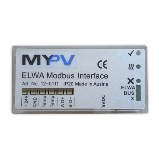
3. Operation displays
The 3 LEDs on the top are the operation displays on ELWA. Functions are described in the ELWA
instruction manual.
The 3 green LEDs underneath show the operation condition of the ELWA Modbus Interface:
No LED light:
all 3 LED blinking:
upper LED light:
middle LED light:
®
ELWA
Modbus Interface Operation Manual, 171018
®
ELWA
Modbus Interface
Operation Manual
no power supply
no connection to the ELWA
connection to the ELWA ok
Modbus order received (timeout approx. 5 sec)
LED operation display
Green (on ELWA)
Yellow (on ELWA)
Red (on ELWA)
green
green
green
Advertisement
Table of Contents

Subscribe to Our Youtube Channel
Related Manuals for MYPV ELWA

Summary of Contents for MYPV ELWA
- Page 1 The 3 LEDs on the top are the operation displays on ELWA. Functions are described in the ELWA instruction manual. The 3 green LEDs underneath show the operation condition of the ELWA Modbus Interface: No LED light:...
- Page 2 Consider polarity! 5. Functionality The ELWA Modbus Interface is a link between the ELWA and a Modbus based bus system. Because of the bus capability the allocation of bus addresses is required when there are multiple devices in operation (register 1030).
- Page 3 DC Breaker status, 0: open, 1: closed 1003 DC Relay status, 0:open, 1: closed 1004 AC Relay status, 0: open, 1: closed, write to register starts/stops ELWA AC relay 1005 Temperature in 1/10°C 1006 Current Water Temp Day minimum in 1/10°C 1007 Current Water Temp Day maximum in 1/10°C...
- Page 4 1021 ELWA Modbus Interface temperature sensor in 1/10°C 1022 ELWA Modbus Interface boost temperature control setting in 1/10°C inactive (factory preset), start boost at setting – 40 (4°C hysteresis), stop boost at setting 1-700 set register 1020 to >1440 if 1022 is >0.
Need help?
Do you have a question about the ELWA and is the answer not in the manual?
Questions and answers