Table of Contents
Advertisement
Quick Links
Advertisement
Table of Contents

Related Manuals for IMS LUND DCT-6Li

Summary of Contents for IMS LUND DCT-6Li
- Page 1 LUND DCT6LI FIELD MANUAL AND TROUBLESHOOTING GUIDE...
-
Page 2: Table Of Contents
LUND DCT-6Li Field Manual and Troubleshooting Guide Contents Overview of Terms .................................. 2 Power System ..................................5 Power System Access ................................5 PowerVar Inverter ................................6 Power-Sonic LiFe Battery ..............................8 Components .................................... 9 Lift Mechanism ..................................9 Power Cord ..................................10 Troubleshooting .................................. -
Page 3: Overview Of Terms
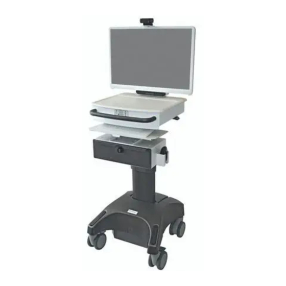
Overview of Terms Power System Controller Remote User Interface (RUI) Slide out Keyboard Tray Combi-Cam Drawer Lock Optional Drawer 75-100mm VESA Display Mount Accessory Mounting Holes Combi-Cam CPU Compartment Lock AC Cord Holder Optional Wire Basket... - Page 4 Remove (4) 8-32 Dual AC outlet from Screws for wire access Power module USB Comm cable for power module Lift control switch RSI cables AC Coil Cord from power module Note: Install from the top down. Lift control switch wire to lift controller...
- Page 5 Universal mounting Optional wire rail basket Adjustable keyboard tray for flat or ergonomic inverted positions...
-
Page 6: Power System
Power System Power System Access To access the battery, power cord, power module, and wiring, remove the (6) Philips head screws surrounding the base: The power cord can be replaced after removing the rear screw and lifting the access panel. -
Page 7: Powervar Inverter
PowerVar Inverter The inverter is secured to the base of the cart by (4) Philips head screws at the base. - Page 8 The front panel has the termination points for the power/status panel, the battery communications cable, and the power connections to and from the battery and cart.
-
Page 9: Power-Sonic Life Battery
Power-Sonic LiFe Battery The Lithium Iron Phosphate battery is secured by the foam that it is set in. The wiring to the battery terminals should be disconnected before the battery can be removed. The red fuse holders contain a 40A fuse between the battery and power module, and a 10A fuse between the battery and lift control relays. -
Page 10: Components
Components Lift Mechanism The lift control board is located in the box underneath the worksurface, on the back of the lift column. Red/Black 12V power from LiFe battery Lift Control switch connector (RJ45 – P2) 30A Motor control relays Lift motor connector (P1) -
Page 11: Power Cord
Power Cord The power cord can be easily replaced after removing the access panel screw at the rear of the cart base. Compress the cable retention insert and pull it out. -
Page 12: Troubleshooting
Troubleshooting NOTE: PowerVar’s MPMView software is crucial for troubleshooting power system (inverter/charger and battery) issues. This software can be downloaded here: http://connectivity.powervar.com/mpm/download.asp MPMView software manual can be downloaded here: MPMView Dropbox link Basic Troubleshooting Problem Possible Cause Action you should take MPM does On/Off button is not pressed long Press and hold the On/Off switch for... - Page 13 Low Battery Conditions Low battery (yellow) Low-battery-critical (red) conditions will flash the LED in the “ tank” position, yellow or red according to the severity… Low battery threshold conditions will also cause the Clinic View application to open automatically to notify the cart user of the time remaining and charge level.
- Page 14 MPM View Battery Diagnostics Values This table describes each of the values presented on the Battery Diagnostics Information screen. Value SMBus Description Function Code Returns the predicted remaining battery capacity expressed as SOC Relative RelativeStateOfCharge() 0x0d a percentage of FullChargeCapacity() (%). The predicted remaining battery capacity expressed as a percentage of DesignCapacity().
-
Page 15: Table Of Condition Codes
Table of Condition codes The table below lists the specific conditions and what they mean. The “Code” is the number included in the Event Log alarm description. Code As displayed in MPM View What it means Battery Charge level warning for low battery charge level. Is triggered Threshold: Low when either threshold for % charge or estimated minutes is reached. - Page 16 Code As displayed in MPM View What it means Input frequency out of range This alarm is raised if the frequency of the input AC power to 30-189 the MPM unit is out of range and the output can only be supplied from battery power.
Need help?
Do you have a question about the LUND DCT-6Li and is the answer not in the manual?
Questions and answers