Table of Contents
Advertisement
Quick Links
Advertisement
Table of Contents

Summary of Contents for Edimax SB-1002W
- Page 1 SB-1002W Quick Installation Guide 12-2019 / v2.0...
-
Page 2: Table Of Contents
Contents I. Safety Information & Reminder......3 II. Product Information ..........4 II-1. Package Content ................4 II-2. System Requirement ............... 4 II-3. LED Indicator ................... 5 II-4. Hardware Interface ................. 7 III. Hardware Installation ..........8 III-1. RS485 Terminal Wire Connection ..........10 IV. -
Page 3: Safety Information & Reminder
Unable to follow the above-mentioned guideline may reduce machine lifetime. You can find all supporting documents from the link below or via QR Code: https://www.edimax.com/download (Once you’ve visited the Edimax official website, please enter model no. “SB-1002W” into the search box to search for your product.) -
Page 4: Product Information
II. Product Information II-1. Package Content Signal Board Quick Installation Power Adapter Guide II-2. System Requirement - Edimax AirBox air quality detector installed. - Internet with Wi-Fi connection (802.11n). - Computer or mobile device with web browser. -
Page 5: Ii-3. Led Indicator
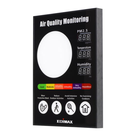
II-3. LED Indicator Current PM2.5 Color LED Indicator (PM2.5) Current Temperature Current Humidity Air Quality Level Color Recommend Action Indicator (PM2.5) LED Status II-4. Color Status Description White Flash Resetting to factory default. Flash Wi-Fi is not connected. Blue Flash Signal board is not connected to the airbox. - Page 6 NOTE: PM2.5 range and recommend action are subject to the local air quality regulations.
-
Page 7: Ii-4. Hardware Interface
II-4. Hardware Interface Description Default Button Reboot Button Power Jack RS485 Terminals Wall-Mount/ Hanging Hole... -
Page 8: Hardware Installation
III. Hardware Installation Make sure your AirBox air quality detector is installed before setting up. Connect the power jack: 1. Unscrew the back cover screw and connect the power supply. 2. Make sure the warning rubber is pulled in the signal board. - Page 9 3. Screw the back cover, power on signal board and check the screen for any abnormality. Note: Make sure the power supply is pulled underneath the RS485 and make sure both are connected properly.
-
Page 10: Iii-1. Rs485 Terminal Wire Connection
RS485 Terminal Wire Connection III-1. If you would like to connect the signal board to the AirBox air quality detector through the RS485 terminal instead of Wi-Fi, please go through the following steps before screwing the back cover. Connect the connection wires to signal board’s RS485 terminal and screw the wires tightly. - Page 11 Wall-mount or hang your signal board on the wall and power on the signal board. The back Screw the wall-mount screws on the wall and hang the signal board. Power on the signal board and check the screen for any abnormality. Note: ˙...
-
Page 12: Wi-Fi Connection
Wi-Fi Connection Supported AirBox: AI-1001W V2 - AI-2002W AI-1001W V3 - AI-2003W AI-1001W V4 - AI-2004W Network Diagram:... -
Page 13: Iv-1. Connect Signal Board To The Airbox (Wi-Fi Setup)
IV-1. Connect Signal Board to the Airbox (Wi-Fi Setup) Please follow the steps below to connect the signal board to the airbox via Wi-Fi: 1. Connect the device either through the mobile phone or computer to the Wi-Fi SSID of your signal board (EdimaxSB.Setup_XX). Please find the unique SSID of your signal board on the product label. - Page 14 4. Click the “OK” button. NOTE: Signal board will disconnect and restart after clicking the “OK” button. Please refresh the page after the device reboot. NOTE: Connection status shows connected if the device is successfully connected. 5. Go to the “DATA SOURCE”page.
- Page 15 Wi-Fi SSID must be the same as the signal board Wi-Fi SSID. NOTE: You may follow the instructions given in Airbox QIG or manual to install the airbox. Please visit our website https://www.edimax.com/edimax/global/ to download the latest version Airbox QIG.
- Page 16 8. Go to “DATA SOURCE”. 9. Click the “REFRESH AIRBOX LIST”button.
- Page 17 4. Select the airbox by using the dropdown menu. And enter the airbox password. 3. Click the “OK” button. NOTE: Please refresh the page after clicking the “OK” button. And wait about 27~35 seconds for the setup to complete.
-
Page 18: Rs485 Connection
V. RS485 Connection Supported AirBox: - AI-2003W - AI-2004W Network Diagram: NOTE: Before setting up, please check if the signal board is connected to the airbox through RS485. You may refer to Pg. 10 for more details. -
Page 19: V-1. Connect Signal Board To The Airbox (Rs485)
V-1. Connect Signal Board to the Airbox (RS485) Please follow the steps below to connect the signal board to the airbox via RS485, 1. Open a browser and login the default IP address “192.168.4.1” of the signal board. 2. Go to the “DATA SOURCE” page. 3. -
Page 20: Wi-Fi Ap Display Mode
WI-FI AP Display Mode In Wi-Fi AP display mode section you can decide to show, close or close the Wi-Fi SSID. - Show: You can configure your signal board to show the SSID. - Hide: You can configure your signal board to hide the SSID. - Close: Disable Wi-Fi SSID. -
Page 21: Firmware Upgrade
VII. Firmware Upgrade Please follow the instructions below to upgrade the firmware, 1. Go to the “FIRMWARE UPDATE” page. 2. Select the *.bin file by clicking the browsing button. - Page 22 1. Click the “UPDATE” button. NOTE: EdiMaxSB.Setup_XX Wi-Fi will be disconnected and resumed after firmware update. Please ensure to refresh the page after upgrading the firmware.
-
Page 23: Factory Default
VIII. Factory Default If you experience problems with your signal board, you can reset the signal board back to its factory default settings. There are two ways to reset the device to default settings. Hardware: Please follow the steps below: 1. - Page 24 Software: Please follow the step below: 1. Click the “RESET” and “OK” button to factory reset on the device.
-
Page 25: Reboot The Device
IX. Reboot The Device Please follow the steps below to reboot the signal board: 1. Press the reboot button. Reboot Button...
Need help?
Do you have a question about the SB-1002W and is the answer not in the manual?
Questions and answers