Table of Contents
Advertisement
Quick Links
Advertisement
Table of Contents

Related Manuals for InkJet DuraCode Series


Summary of Contents for InkJet DuraCode Series
- Page 1 DuraCode Series Continuous Inkjet Printer OPERATION MANUAL www.inkjetinc.com | 1-800-280-3245 Compliance Information This equipment has been tested and found to comply with the limits for a Class A digital device, pursuant to part 15 of the FCC Rules. These limits are designed to...
- Page 2 provide reasonable protection against harmful interference when the equipment is operated in a commercial environment. This equipment generates, uses, and can radiate radio frequency energy and, if not installed and used in accordance with the instruction manual. Operation of this equipment in a residential area is likely to cause harmful interference, in which case the user will be required to correct the interference at his own expense.
-
Page 3: Table Of Contents
Content About the DuraCode DURACODE 200 SERIES KEYPAD Printer ------------------------------------------ 1 1. Safety Guidelines ------------------------------------- 2 1.1 Introduction ------------------------------------------------------------------------ 2 1.2 General Safety Guidelines ---------------------------------------------------- 2 1.3 Fluid Safety Guidelines -------------------------------------------------------- 3 1.4 In Case of Emergency ---------------------------------------------------------- 3 2. Introduction -------------------------------------------- 4 2.1 Appearance overview ----------------------------------------------------------- 4 2.2 Control Panel --------------------------------------------------------------------- 4 2.3 Printhead -------------------------------------------------------------------------- 5... - Page 4 3.1 Commission --------------------------------------------------------------------- 14 3.2 Start The Printer --------------------------------------------------------------- 15 Content 3.2.1 Start Jet ------------------------------------------------------------------ 15 3.2.2 Inkjet Observation ----------------------------------------------------- 16 3.2.3 Drops Observation ----------------------------------------------------- 17 3.3 Stop Jet -------------------------------------------------------------------------- 18 3.3.1 Stop Jet and Clean ---------------------------------------------------- 18 3.3.2 Stop and Clean (Power off during use of the printer) -------- 18 3.3.3 Stop and Clean (long-term stop of use) ------------------------- 18...
- Page 5 3.7.5 Repeat Printing Mode ------------------------------------------------ 36 4. Maintenance ------------------------------------------ 37 Content 4.1 Diagnostic Screen ------------------------------------------------------------- 37 4.2 Failure and warning icons --------------------------------------------------- 38 4.2.1 Failure icons ------------------------------------------------------------- 38 4.2.2 Warning icons ----------------------------------------------------------- 39 4.3 Troubleshooting ---------------------------------------------------------------- 40 4.4 Wash Nozzle -------------------------------------------------------------------- 41 4.5 Ink Jet Alignment -------------------------------------------------------------- 41 4.6 Clean Ink System -------------------------------------------------------------- 42 4.7 Sensor and Encoder Wiring Diagram ------------------------------------ 43...
-
Page 6: About The Duracode Duracode 200 Series Keypad Printer
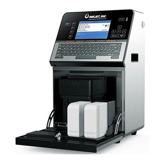
It is used to apply sell-by dates, batch codes, logos, barcodes, and other variable information to a wide range of substrates on the production line using a continuous inkjet printing technology. It is designed with a stainless-steel enclosure with an IP55 rating (International Protection rating against dust and water). -
Page 7: Safety Guidelines
1. Safety Guidelines 1.1 Introduction The intended use of the DuraCode series printer is to print information directly onto a product. Use of this equipment in any other fashion may lead to serious injury. The safety guidelines provided in this manual are intended to educate the operator on all safety issues, so that the printer is operated in a safe manner. -
Page 8: Fluid Safety Guidelines
• BEFORE YOU START read the Material Safety Sheets. If Material Safety Sheets have not been supplied, please contact InkJet Incorporated for a copy. • The printer must be installed in a well-ventilated area when working on the printer, or with inks and solvents. -
Page 9: Introduction
2. Introduction 2.1 Appearance overview Right View Front View Left View Introduction: 1. Power button 2. Upper:Electronics Compartment 、Control Panel 3. Lower:Ink Compartment 4. Connector Panel 5. Umbilical 2.2 Control Panel Page 4... -
Page 10: Printhead
2.3 Printhead Last Chance Filter Nozzle Connector Printhead type Nozzle Charge Electrode Nozzle Connector Deflection Plate Gutter Pipe 2.4 Ink Core * Exhaust Air Switch Condenser Cover Manifold Filter Gear Pump Addition Pump Drain Pipe Flushing Pump * Exhaust Vent Plug Ink Core(Front View) Ink Core(Back View) * Please remove the exhaust vent plug and turn on exhaust... -
Page 11: Main Screen
2.5 Main Screen The main screen is the default screen after the printer powered on: Instructions: 1. The current status description area of the device; 2. A shortcut function keypad includes an user-defined function; 3. The name of the current message ; 4. -
Page 12: Menu Analysis
2.6 Menu Analysis 2.6.1 PRINT DATA 1. It is used to select and recall the stored messages , which is equivalent to the “F2 Select Message” on the main screen. 2. Used to create and edit saved messages. 3. Used to set the default message parameters. 4. -
Page 13: Print Set
2.6.3 PRINT SET 1. Used to enable or disable the printing function. if set to "Disable", the printer will disable the printing function and prompt "High voltage not activated" in the status bar. 2. It is used to select the printing quality, standard and high quality 01~15. The higher the high quality selection, the better the printing quality will be, but the slower the printing speed will be. -
Page 14: Ink System
4. Used for cleaning umbilical , only for commissioning engineers to use when debugging. 5. It is used to quickly start the jet, without auto cleaning. 6. For quick stop inkjet without auto cleaning. 7. For setting the ink type, built-in B600, 601, A630, 680, 619, 669, 2630, 2631, 263, 273 and 630. -
Page 15: Machine Set
2.6.5 MACHINE SET Configuration 1. Used to disable the automatic shutdown caused by charge fault. 2. Used to disable the automatic shutdown caused by the gutter fault. 3. used to set the modulation value, auto mode only takes effect during startup. 4. -
Page 16: F4 Password
2.6.6 F4 Password Only "Enter Password" menu is displayed before the password is entered. 1. Used to enter password; 2. Used to exit the password to level 0 (The lowest permission). 3. Used to set the password protection level of each function of the system. 4. -
Page 17: Photocell 1 Set
2.6.8 Photocell 1 Set 1. Select photocell 1 to be active by high or low level when triggering printing. 2. The way of the external photocell triggers printing, Gate or Trigger optional . 3. Within this time, the time interval between the trigger level and the trigger level can be obtained again (such as avoiding secondary sensing in the same product);... -
Page 18: Specifications
2.7 Specifications Electrical specifications Voltage 100V-240V AC Frequency 50Hz-60Hz Energy consumption 120(W) maximum value Weight Net weight 27KG Dimensions Cabinet 345L * 286W * 570H Printhead diameter 35mm / 41mm Printhead length 260mm / 250mm Nozzle size 70,60,50,40 μm Umbilical length 2700mm Environment specifications Operating temperature... -
Page 19: Printer Operation
3. Printer Operation 3.1 Commission Printer needs to be filled with ink and exhaust air before use. 1. Open the lower cabin door and install the correct ink and makeup to the correct position according to the label . 2. Pull out the ink system, remove the exhaust air plug at the bottom (Refer to step A.)*, and use a screwdriver to open the top exhaust air switch (Refer to step B.)* as shown in figure: B. -
Page 20: Start The Printer
3.2 Start The Printer 3.2.1 Start Jet 1. Connect the printer to an appropriate power source. 2. Open the printer head cover, check various components in the printhead, and check that various components are clean and dry. 3. Put on the printhead cover, press the power button at the right side of the printer, and wait for the screen to enter the main operation interface 4. -
Page 21: Inkjet Observation
3.2.2 Inkjet Observation Side View : Inkjet Charge Nozzle Electrode The inkjet is at the central position of the gutter pipe Front View: The inkjet is about 1/4 of the right side of the gutter pipe Nozzle Charge Electrode Page 16... -
Page 22: Drops Observation
3.2.3 Drops Observation The drops are generated after printer has started normally. It directly affects the printing effect and printing durability. Good drops roughly depend on the following three factors: Appropriate and stable pressure Correct ink viscosity Correct modulation value The observation method is as follows: 1. -
Page 23: Stop Jet
3.3.2 Stop and Clean (Power off during use of the printer) If abnormal stop is caused due to power off, inkjet must be restarted at the earliest time after power on. It shall be normally cleaned and shut down after planned shutdown else some ink tubes of the printer may be blocked, causing permanent damage to the printer. -
Page 24: Create Message
3.4 Create Message 3.4.1 Create a Sample Message For example: Create the following message as follows with a file name “TEST” to create this message: Follow these steps: PRINT DATA menu,select E) Edit/Create Message - Create New 1. Enter the Message, confirm and enter the interface as shown in the following figure: 2. - Page 25 4. Press to select the “R” User Field (refer to 3.5.7 Logo), press the Enter key to insert, as shown below: In the editing interface, the function is “ Insert User Field ”. 5. After the content is entered, press the to switch to the “Save Exit”...
-
Page 26: Create/Edit User Field
3.5 Create/Edit User Field 3.5.1 Time User Field Follow the steps below to create : USER FIELD menu,select E) Edit/Create User Field - N) New User 1. Enter the Field, as shown in the figure below: 2. Input a file name, switch “Attr” to “Time” then confirm , as shown in the figure below: 3. -
Page 27: Additional Remarks For Time User Field
3.5.2 Additional remarks for time user field Definition of Time User Field Code Definition Code Monday to Sunday Year Month Hour Minute Second Week Year Code Month Code Day Code Hour Code Minute Code 1. Actual printing date and time = system current time + number of days of Expiry term. If it is required to print the current time, the Expiry term is set as 0. -
Page 28: Barcode User Field
3.5.3 Barcode User Field The standards of barcode supported by the type include: QR Code (Figure 1), Data Matrix (Figure 2), Code39 (Figure 3), Code128 (Figure 4), EAN8 (Figure 5), EAN13 (Figure 6), EAN128 (Figure 7), UPC-A(Figure 8) Figure 1 Figure 2 Figure 3 Figure 4... -
Page 29: Additional Remarks For Barcode User Field
3.5.4 Additional remarks for Barcode User Field 1. The size (Height x Width) supported by Data Matrix include 10x10, 12x12, 14x14, 16x16, 18x18, 20x20, 22x22, 24x24, 26x26, 32x32, 8x18, 8x32, 12x26, 16x36, 16x48. 2. The size (height x width) supported by QR Code include 21x21, 25x25, 29x29, 33x33. -
Page 30: Counter User Field
3.5.5 Counter User Field 1. Enter the USER FIELD menu,select E) Edit/Create User Field - N) New User Field, as shown in the figure below: 2. Input a file name, switch “Attr” to “Text” then confirm , as shown in the figure below: Instructions of each items refer to “... -
Page 31: Instructions For Items In The Counter
3.5.6 Instructions for Items in the Counter 1. Start value : Start value of the counter. 2. End value : End value of the counter 3. Reset value : Value to be reset when the function of "Reset Counter" of the Photocell 2 is used. -
Page 32: Logo User Field
3.5.7 Logo User Field The Logo User Field can create the customized logo of maximum 34 dots height ( F530/ F530Plus only support 25 dots ). 1. Enter the USER FIELD menu,select E) Edit/Create User Field - N) New User Field, as shown in the figure below: 2. - Page 33 4. After drawing, press the “ " key to set the logo size, as shown in the following figure: Press the CUSTOM button on this interface to pop up the Help window. 5. Complete logo size setting, press Enter to confirm the size, press to save and exit.
-
Page 34: Code User Field
3.5.8 Code User Field This function can integrate multiple User Fields ( Clock, counter and text ) in to generate a code. 1. Enter the USER FIELD menu,select E) Edit/Create User Field - N) New User Field, as shown in the figure below: Enter 2. -
Page 35: External Data User Field
3.5.9 External data User Field The function can receive the external data predefined by the user and print them in sequence. The preparation steps are as follows: 1. Enter the USER FIELD menu,select E) Edit/Create User Field - N) New User Field, as shown in the figure below: Enter 2. -
Page 36: Message Parameters
3.6 Message Parameters 3.6.1 Modify message parameters and contents In the main screen, press the key to enter the interface to modify current message contents and parameters, as shown in the figure; 1. "WYSIWYG" information editing area; 2. Parameter editing area,through to adjust parameters, width and delay parameters can be input directly. -
Page 37: Print Mode Setting
3.7 Print Mode Setting 3.7.1 Single Printing Mode The mode is commonly used for beer, beverage, food, daily necessities and other familiar industries . One trigger one printing. 1. Press PRINT SET button to enter the following setting interface: The GRAY options indicate that the setting is invalid for the "Single Print" mode. 2. -
Page 38: Continuous Printing Mode
3.7.2 Continuous Printing Mode The mode is commonly used for building materials, pipe, steel material and other industries. The common feature is continuous processing, messages automatic interval printing. 1. Press PRINT SET button to enter the following setting interface: The GRAY options indicate that the setting is invalid for the "Continuous Print" mode. 2. -
Page 39: Measure Mode
3.7.3 Measure mode The mode is commonly used in the wire cable, pipe and other industries requiring labelling of number of meters , the encoder must be used . 1. Press PRINT SET button to enter the following setting interface: The GRAY options indicate that the setting is invalid for the Measure Mode. -
Page 40: Traverse Printing Mode
3.7.4 Traverse Printing Mode The mode is commonly used in electronics, label printing, egg and other industries, and provides highly-efficient production mode for the array type printing. PRINT SET 1. Press button to enter the following setting interface: The GRAY options indicate that the setting is invalid for the Traverse Mode. 2. -
Page 41: Repeat Printing Mode
3.7.5 Repeat Printing Mode In this mode you can set the specific numbers of printing per trigger. 1. Press PRINT SET button to enter the following setting interface: The GRAY options indicate that the setting is invalid for the Repeat Mode. 2. -
Page 42: Maintenance
4. Maintenance 4.1 Diagnostic Screen In any interface, press button to enter the diagnosis screen, and the interface is as follows: EHT 65 113 1. Ink pressure and Ink Temperature. 2. Temp Cabinet: Actual upper cabinet temperature. Head : Heater temperature. 3. -
Page 43: Failure And Warning Icons
4.2 Failure and warning icons 4.2.1 Failure icons Icon Name Fault cause Solution Check the leaking position. Please Ink system leak consult the service engineer The solvent components in Mixing the Mixer are vaporized It is suggested to drain the old ink, Tank after long-term storage of and fill the new ink. -
Page 44: Warning Icons
4.2.2 Warning icons Icon Name Instructions for warning Jet printing The ink in the system is circulating and in good condition, operation the printer is ready for printing Jet printing The ink in the system is not circulating, the printer is in stop stopped state, and printing cannot be conducted Insufficient... -
Page 45: Troubleshooting
Clean the gutter pipe deposited with ink, check and adjust the ink position in the Ink deposited on the gutter pipe gutter. Refer to "3.2.2 Inkjet Observation ". The print varies in width and Determine the printing position again or... -
Page 46: Wash Nozzle
4.4 Wash Nozzle When the nozzle is blocked, manual cleaning is required for the function. The operation procedures are as follows: ,select and perform F) Wash Nozzle program. 1. Press INK SYSTEM 2. After the program is started, manually clean the position shown in the following figure with cleaning agent. -
Page 47: Clean Ink System
4.6 Clean Ink System INK SYSTEM button , perform the C) Clean Ink System program ,finish the Press drain operation according to the system prompt. Page 42... -
Page 48: Sensor And Encoder Wiring Diagram
4.7 Sensor and Encoder Wiring Diagram 4.7.1 Sensor Diagram 4.7.2 Encoder Diagram 3. 1RQH Page 43... - Page 49 Inkjet Inc. reserves the right to modify the technical characteristics of the product without prior notice.
Need help?
Do you have a question about the DuraCode Series and is the answer not in the manual?
Questions and answers