Advertisement
Quick Links
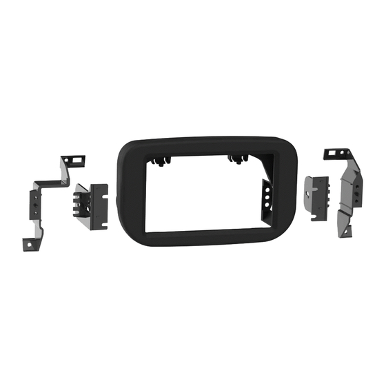
KIT COMPONENTS
• A) Radio trim panel • B) Radio housing • C) Sub dash brackets • D) Radio brackets • E) Panel clips (3) • F) #8 x 1/2" Phillips screws (4)
A
B
Ford Transit
2020
KIT FEATURES
• ISO DDIN radio provision*
• Painted scratch resistant matte black
* This kit is designed for an ISO DDIN radio which have an "L" shaped chassis
design, with the radio chassis at the bottom of the screen,
or Pioneer modular 6.8" radios.
Refer to the radio manufacturer for current models
C
D
I N S TA L L AT I O N I N S T R U C T I O N S
TABLE OF CONTENTS
Dash Disassembly ..................................................2
Kit Preparation .......................................................3
Kit Assembly
–ISO DDIN radio provision .....................................4
–Pioneer Modular radio provision .......................5
TOOLS REQUIRED
E
• Panel removal tool • 9/32" socket
• Phillips screwdriver • Cutting tool
F
50-640
Attention!
Let the vehicle sit with the key
out of the ignition for a few minutes before
removing the factory radio. When testing the
aftermarket equipment, ensure that all factory
equipment is connected before cycling the
key to ignition.
Advertisement

Summary of Contents for InCarTec 50-640
- Page 1 50-640 I N S TA L L AT I O N I N S T R U C T I O N S Ford Transit 2020 TABLE OF CONTENTS Dash Disassembly ..........2 Kit Preparation ............3 KIT FEATURES Kit Assembly –ISO DDIN radio provision ........4 •...
- Page 2 DASH DISASSEMBLY 1. Unclip the trim behind the radio display, 4. Remove (4) 9/32” screws securing the then remove (3) 9/32” screws exposed. radio display mount, then remove. (Figure A) (Figure D) 2. Slide the radio display up and out, then 5.
- Page 3 KIT PREPARATION 1. Attach the (3) included panel clips to the radio trim panel. (Figure A) 2. Cut and remove the two lower mounting Remove shaded areas tabs from the inside of the factory dash panel radio opening. (Figure B) Continue to Kit Assembly (Figure A) (Figure B)
- Page 4 KIT ASSEMBLY 5. Locate the factory wiring harness and Bottom chassis radio provision antenna connector in the dash and 1. Secure the sub-dash brackets to the complete all necessary connections to dash using the factory screws. (Figure A) the radio. Test the radio for proper 2.
- Page 5 KIT ASSEMBLY Pioneer Modular DDIN radio provision 6. Locate the factory wiring harness and antenna connector in the dash and Note: For steps 2 and 3, reference the complete all necessary connections to installation manual provided with the radio the radio. Metra recommends using for which hardware to use.