Table of Contents
Advertisement
Quick Links
Advertisement
Table of Contents

Summary of Contents for Preston Cinema Systems F I + Z
- Page 1 F I + Z Lens Control DRAFT Rev 4.02...
-
Page 2: Table Of Contents
Preston Cinema Systems 1659 Eleventh Street Santa Monica, CA 90404 Table of Contents I. Introduction A. System B. Hand Unit 3 C. Micro Force Zoom D. Remote Iris Box E. Optional Wireless Units F. MDR3 G. DM-1X, DM-2, DM4X motors II. FI+Z Basic Operation Summary A. Motor Driver and Digital Motor set-up B. -
Page 3: Introduction
VI. Camera and Lens Installation p-21 A. 15mm Arri B. 19mmArri C. Panavision D. Gears Battery Packs and Charger p-22 VII. VIII. Technical Information p-23 A. FCC Statement B. Connector Pin-Outs p-24 1. Hand Unit 2. MDR3 C. MDR3 Camera Cable list p-24 D. - Page 4 The HU3 and MDR3 can also be connected through a cable link using the main command cable. This provides high reliability communication over long distances (1km). To address the metadata requirements of CGI, the MDR3 has motor position and camera data, as well as focus, iris and zoom data in conventional units available at the serial port.
-
Page 5: Z Basic Operation Summary
F. The Motor Driver (MDR3) supports 4 motor channels and camera run/stop. The 30 channel transceiver allows the simultaneous operation of both the Hand Unit 3 as well as the optional wireless hand units listed previously. An integral voltage booster allows for operation over a voltage range of 11 –... - Page 6 HU3 Set-up a. Install the FM50/FM500H battery. b. Press the Power Switch momentarily. The main display screen will appear. Radio Channel footage Focus Ring Letter Signal Strength bars Battery Charge Lens Selection Shows focus distance Shows focus knob All functions are accessed through the Menu key in digital format setting as bargraph...
- Page 7 The Signal Strength bars will appear. To return to the main menu, press the Nav key left. e. To use a blank focus marking ring, turn off the Focus mapping: Press the Menu key. Select Lens. If the focal length and serial number of a lens appears to the right of “Lens”, ...
-
Page 8: Hand Unit
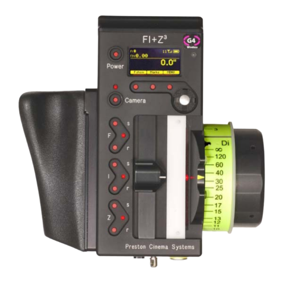
Hand Unit 3 Functions Microwave Antenna Cover Ambient Light Sensor OLED Display Splash Resistant Housing Hand Unit Power 3 x Soft Keys Camera R/S with LED 4-way Navigation “Nav” Key Enter & (in center Pre-printed Focus Marking Ring Molded Hand Grip Focus Knob with soft Urethane Knob Gri Iris Slider... - Page 9 III. Hand Unit 3 . Detailed Description A. Grip Configurations 1. The Hand Unit can be set-up with a molded Hand Grip for Focus and Iris control or with the Hand Grip replaced by a flat cover to accommodate a bracket and Micro Force zoom control.
-
Page 10: Hu3 Set-Up And Operation
Set-Up and Operation Main Display Screen. Press the Power Switch momentarily. The OLED display will show the Main Display Screen : Radio Channel footage Focus Ring Letter Signal Strength bars Battery Charge Lens Selection Shows focus distance Shows focus knob All functions are accessed through the Menu key in digital format... -
Page 11: Footage Counter
Footage Counter menu Movement Selection Film camera fps and shutter angle control are not supported with the MDR3, and the corresponding menu items will not be active when the HU3 detects connection to an MDR3 unit. 5. The Camera selection (Fig 5.1) provides for control of both camera speed and shutter angle for those cameras supporting remote operation (MDR2 only). - Page 12 All lenses Choose key brings up the list of folders containing lens data (Fig 6.2). The folder contains data on all of the lenses stored in the HU3 lens library. The Library stores up to 255 lenses. Next brings up the contents of the selected folder (Fig 6.3). My list A, B The folders , and...
- Page 13 Press the New Lens key (Fig 6.7) and you will be asked to select the focal length (Fig 6.10), and Serial Number (Fig 6.11). When finished, press Next and the lens name (18mm s/n 123) appears in the lens type folder (Fig 6.12). Note that the lenses are automatically sorted in ascending values of the focal length.
- Page 14 After the tenth point is entered (Fig. 6.17, 6.20), the lens description is shown to the right of the Lens entry of the Menu (Fig. 6.21). The letter “c” to the right of the lens description indicates that the lens has been calibrated. The main screen (Fig. 6.22) shows the lens information.
- Page 15 used. Choosing the Di ring instead would make the entire rotation of the focus knob available and double the spread of distances, dramatically improving the precision. Note that any focus ring can be used with any calibrated lens. 7. The Mode (Fig. 7.1) has two functions. The first allows the four MDR motor channels, focus, iris, zoom and auxiliary to be assigned to user-designated Hand Unit controls.
- Page 16 In situations where the lens setting must be controlled only by the single function hand unit and not the HU3, the corresponding HU3 channel should be set to “Off”. Zoom Mode Set-Up Fig. 7.5 Fig 7.6 Fig. 7.7 (Zoom modes are only supported for the MDR2) To choose a Zoom Mode press the Set-Up key (Fig.
-
Page 17: Lens Limits
Region key (fig.3, 4) adjusts the output power of the microwave link to comply with local regulations. Fig. 8.4 Fig.8.5 Fig. 8.6 OPTION (Fig. 8.6) selections consist of selecting distance units and knob direction. Use the Navigation key to select the desired function. The default knob direction is CW. Optional labels for the focus rings are available for CCW direction use. -
Page 18: Software Updates
Lens limits can be used to lock a motor to a given position. This is done by setting a zero- span, where the beginning and end of the range are the same point. To lock a motor, position the motor to the desired point and press the set button twice. 11. -
Page 19: Remote Iris Unit
12. Remote Iris Unit A receptacle is provided on the bottom of the HU3 for an external, cable connected, iris control. When the external iris control is connected, the slide control on the FIZ will be disabled. Fig. 12.1 Remote Iris Box p/n 4020 13. - Page 20 The four channel Motor Driver (MDR3) is responsible for driving the motors, providing control signals to the camera, and transferring camera operating data to the wireless network through the transceiver module. The MDR3 uses a lens calibration sequence to determine the mechanical limits of the zoom, focus, and iris rings of the lens.
-
Page 21: Digital Motors
To initiate the update, open the MRD3 update program on your computer. The program CD and a USB cable are included with the MDR3. Remove power from the MDR3. Connect the USB cable between the computer and MDR3 USB receptacle. Open the MDR3 update program. - Page 22 The integral swing arm has rosettes on two sides. This permits the motor to be mounted horizontally (above, left) or vertically (above, right). The two adjustable handles lock the rosette position and the motor bracket to the matte box support rod. Important tip: to prevent the motor position from changing as the handles are tightened, first tighten the handle which clamps the motor to the rod and then tighten the rosette handle.
- Page 23 D. Standard motor output gears are .80m. They are available in .25” and .50” face widths. These standard gears are designed to accept additional “step-up” gears for use with lenses having alternate gear pitches. Motor Gear/Application 4221 0.8m .50” wide 4231 48DP .25”...
- Page 24 * Connect the equipment into an outlet on a circuit different from that to which the receiver is connected. * Consult the dealer or an experienced radio/TV technician for help. This equipment has been verified to comply with the limits for a class B computing device, pursuant to FCC Rules. Operation with non‐approved equipment is likely to result in interference to radio and TV reception. The user is cautioned that changes and modifications made to the equipment without the approval of manufacturer could void the user's authority to operate this equipment. This device complies with Part 15 of the FCC Rules. Operation is subject to the following two conditions: (1) This device may not cause harmful interference and (2) This device must accept any interference received including interference that may cause undesired operation. FCC RF EXPOSURE STATEMENT To satisfy RF exposure requirements, this device and its antenna must operate with a separation distance of at least 20 cm from all persons and must not be co‐located or operating in conjunction with any other antenna or transmitter. B. Connector pin-outs 1. Hand Unit Connectors Command Serial Zoom Remote Iris 5-pin 4-pin 6-pin 3-pin +12V +PWR...
- Page 25 Command Serial Power Motor Camera 6-pin 4-pin 2-pin 7-pin 10-pin +12V Batt(-) Motor(+) Batt(-) 24V 0.2A Batt(+) Motor(-) Serial Serial 1 Serial In Encoder A Serial Serial1 Serial Out Batt(+) Camera R/S Encoder B Common R/S Motor ID Camera ID Camera ID rtn C.
Need help?
Do you have a question about the F I + Z and is the answer not in the manual?
Questions and answers