Advertisement
Available languages
Available languages
Instruction / Installation Sheet
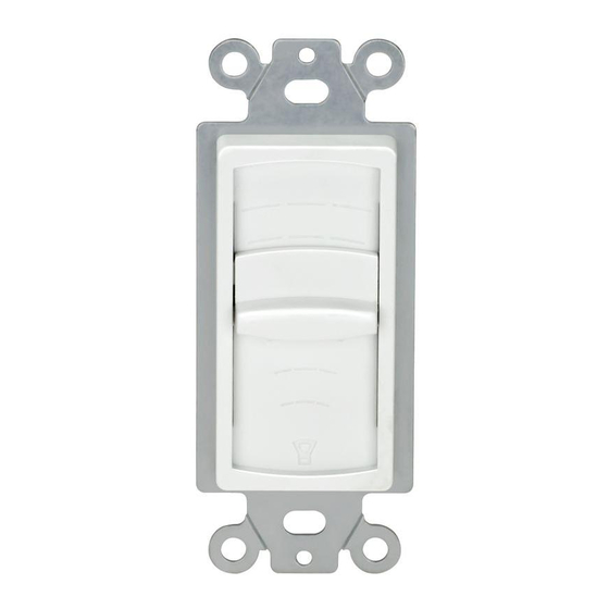
Speaker Volume Control
No. 5535
Parts Included:
● One (1) Speaker Volume Control
● One (1) Connector Block
● Two (2) Screws
INSTALLATION PRECAUTION: ALWAYS FOLLOW THE NEC AND LOCAL ELECTRICAL CODES/REGULATIONS.
WARNING: MAXIMUM AMPLIFIER POWER IS 100 WATTS PER CHANNEL. USING HIGHER AMPLIFICATION POWER CAN CAUSE DAMANGE
TO VOLUME CONTROL OR SPEAKERS.
Before making any connections to the Speaker Volume Control, please note that the left (-L+) and right (-R+) channels are isolated from one another in
order to prevent instability when used with certain types of amplifiers that have a common ground (or a floating ground). If your amplifier has a common
ground between the left (-L+) and right (-R+) channels, a three wire system should be used between the amplifier and Speaker Volume Control. With a
three wire system, a jumper wire needs to be connected between the left (-L) and right (-R) grounds. If one of the grounds remains open there will be no
output on the ungrounded channel at any volume control setting.
Impedance Matching: A separate impedance matching module or speaker selector box is required when multiple volume controls are used with
one amplifier.
Installation Instructions:
1. Select location for mounting the Speaker Volume Control.
NOTE: The Speaker Volume Control has a higher than average depth and the use of a deep electrical box or low voltage mounting bracket is
recommended.
2. Strip and remove speaker wire insulation approximately 1/4" (.63 cm) to reveal bare wire at the ends. Twist any loose strands of the bare wire tightly
to make connections.
NOTE: When running wire up to 30' (9.1 m), use at least 16 AWG speaker wire. When running wire longer than 30' (9.1 M), use 14 AWG - 12 AWG
speaker wire.
3. Insert the wires from the amplifier into the "FROM AMP" positions of the Connector Block. Insert positive-to-positive and negative-to-negative. Use
small flat head screw driver to tighten screws to hold the speaker wire in place. Make sure there are no stray wire strands that might cause a short
circuit. The screw terminal of the Connector Block must engage the bare wire and not the speaker wire insulation in order to make a secure
connection.
4. Connect speaker wires to the "TO SPEAKER" positions of the Speaker Volume Control and tighten screws to hold in place.
5. Install the Speaker Volume Control in its predetermined location ensuring that it is facing upwards (TOP is marked). To avoid possibly damaging your
speakers, start with the Speaker Volume Control at the lowest volume position. Slowly raise the volume in order to verify operation.
CE Tech's products shall be installed and used only as indicated in CE Tech's product instruction sheets.
Tools Needed:
● Phillips Head Screw Driver
● Small Flat Blade Screw Driver
● Wire Cutter and/or Wire Stripper
DISTRIBUTED BY: HOME DEPOT U.S.A., INC.
2455 PACES FERRY RD., N.W.
ATLANTA, GA 30339
FOR ASSISTANCE, CALL:
1-800-394-7519
HOMEDEPOT.COM
MADE IN CHINA
5535 Rev. 1
Advertisement
Table of Contents

Related Manuals for CE Tech 5535

Summary of Contents for CE Tech 5535
- Page 1 Speaker Volume Control at the lowest volume position. Slowly raise the volume in order to verify operation. CE Tech’s products shall be installed and used only as indicated in CE Tech’s product instruction sheets. 5535 Rev. 1...
- Page 2 Para evitar un posible daño a los altavoces, comienza con el Control de Volumen del Altavoz en la posición más baja. Sube el volumen lentamente para verificar si funcionan. Los productos CE Tech deben instalarse y usarse según se indica en las hojas de instrucciones de productos CE Tech. 5535 Rev. 1...
Need help?
Do you have a question about the 5535 and is the answer not in the manual?
Questions and answers