Table of Contents
Advertisement
Quick Links
Advertisement
Table of Contents

Related Manuals for electronica EL 750

Summary of Contents for electronica EL 750
- Page 1 EL 750 Operational Manual Digital Readout System Machine Tool...
-
Page 2: Table Of Contents
EL750 Table of Contents INTRODUCTION ..............................4 DRO SPECIFICATIONS ............................5 READ BEFORE PROCEEDING ..........................6 GETTING STARTED ............................... 7 ................................7 RONT ................................8 ..............................9 EYBOARD LAYOUT ................................10 ................................. 12 OWER UPPLY ............................. 12 NCODER ONNECTIONS UP ................................13 OWER ................................ - Page 3 EL750 8.1.5 Grid ................................45 8.1.6 Frame: - ............................... 46 8.1.7 Arc Contouring: - ............................47 8.1.8 R- Function ..............................48 8.1.9 Pocket: - ..............................50 8.1.10 Slot ................................. 50 8.1.11 Polar Coordinates ........................... 52 8.1.12 Axis Summing ............................52 8.1.13 Zero Approach ............................
-
Page 4: Introduction
1. Introduction Congratulations on purchasing EL750 series Digital Readout System (DRO) from Electronica Mechatronic Systems. Our DRO incorporates the latest state of the art technology; giving you world class features which help in improving productivity, reducing rejection and at the same time giving ease of operation to user with its ergonomic design. -
Page 5: Dro Specifications
EL750 2. DRO Specifications Electrical: Mains Supply: 90 VAC to 265 VAC (50 / 60 Hz) Fuse Rating: 800mA Slow Blow 20mm Power Consumption: 15W SMPS Standard Compliance: EMC and Low Voltage Compliance BS EN61326 RoHS Environmental: Storage Temperature: -20ºC to +70ºC Operating Temperature: 0ºC to 50ºC Relative Humidity:... -
Page 6: Read Before Proceeding
EL750 3. Read Before Proceeding The EL750 DRO is sophisticated electronic equipment and should be carefully handled to avoid any damage. The rated supply to DRO should be within specified limits and should not be exceeded under any circumstances. Doing so may cause irreversible damage to DRO. -
Page 7: Getting Started
EL750 4. Getting Started 4.1 Front View Numeric Axis Keypad Keys Basic Arrow Keys Soft Keys Operation Display P a g e... -
Page 8: Rear View
EL750 4.2 Rear View Manufacturers Auxiliary Fuse (Spare included) Power ON label with Serial Connector 800mA Slow Blow Switch Number Optional 20mm Power Inlet Equipotential Probe Encoder USB B type IEC Connector Point (Ground Connector connector Inputs terminal) P a g e... -
Page 9: Keyboard Layout
EL750 4.3 Keyboard layout Symbols Description ABS / INC Inch / mm FUNCTION KEYS Reference Preset SDM Function Numeric Keys Toggle Sign Decimal Entry NUMERIC KEYBOARD Enter Cancel Navigation Keys COMMON Soft key Selection / Axis Selection OPERATIONS LCD standby Key P a g e... -
Page 10: Soft Keys
EL750 4.4 Soft Keys Description Description Machine reference Height Measurement Homing Corner Measurement Set reference Angle measurement Diameter Skew Measurement Mill/Lathe Tool set Internal measurement Delete tool External Measurement Tool On Datum Tool Off Calculator Vector Angle Calculate SDM ON Diameter Next SDM Internal diameter... - Page 11 EL750 Description Description New job Next arrow Job delete Next hole Linear Compensation Apply the tool Segmented Exit from tool compensation Plane selection Save Edit Multimode Plane Selection Single Position Reset Setup Select Zero Probe measurement 11 | P a g e...
-
Page 12: Power Supply
EL750 4.5 Power Supply The EL750 DRO series uses a Switch mode power supply inside which covers the universal power input range i.e. 90VAC to 265VAC / 50 to 60 Hz. Ensure the input power is within the specifications before powering the unit. The power supply to the DRO should not be given from the same source as that of any high capacity switching / inductive loads to avoid interference. -
Page 13: Power Up
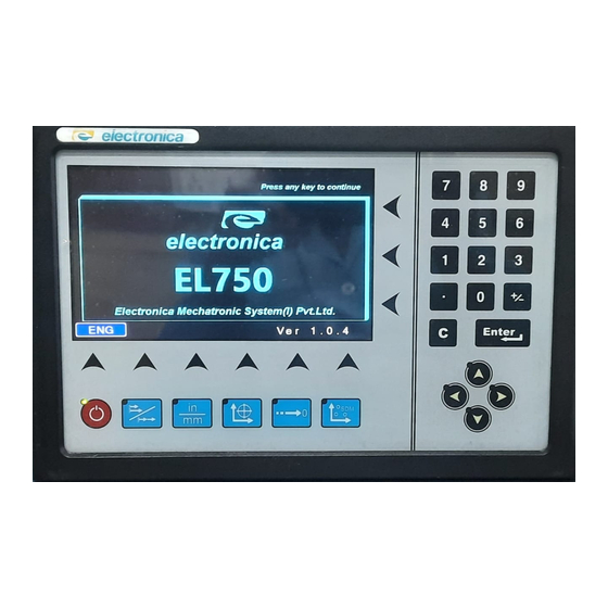
EL750 4.7 Power UP Switch ON the power switch located on the back of the DRO. The DRO will display the power UP message momentarily as shown below *Owing to continuous Research & Development software version may be different than displayed. 13 | P a g e... -
Page 14: Screen Layout
EL750 4.8 Screen Layout Sample screen of EL750 DRO, Labels description is as below. Labels Description Feed rate Tool No. ABS/ Inc mode Inch / MM Axis Label Display Area Soft key notification 14 | P a g e... -
Page 15: Setup
EL750 5. Setup The EL750 setup can be accessed by pressing [ ] key followed by SOFT KEY }. The SETUP mode screen is as shown below. Press [ ] or { key to access the setup. • Different menus can be navigated using [ ] keys. -
Page 16: General Settings
EL750 5.1 General Settings: User Setup Description Parameters Sleep Mode Time Defines Sleep Time Interval in minutes (5 to 120). (min) Key Beep Enable To enable or disable keyboard beep ON or OFF. Zero App. Beep En To enable or disable Zero Approach Beep ON or OFF. This sets a tolerance value for Zero Value in Zero approach Zero App. - Page 17 EL750 Procedure:- 1) Press { } key in “Machine Ref.” in axis settings. “Homing” Message is shown on the screen. 2) Pass the reference mark on the encoder. Here the DRO will reset the axis on the reference mark. 3) Go to the machine reference position and press { 6.
-
Page 18: Axis Specific Settings (Angular Type)
EL750 5.3 Axis Specific Settings (Angular Type): 1. Counts per Revolution. (CPR): This parameter defines the Encoder counts per rotation. Either the operator can enter this value if this is known or there is an automatic calibration process for finding the CPR value. In the automatic process, the user is prompted to pass two reference marks in the same direction. - Page 19 EL750 8. Axis Lock : Two options are possible for this parameter. a. Axis Lock ON b. Axis Lock OFF. Axis Lock ON prevents the operator from axis setting in absolute mode. Only the operator can perform referencing. The default value is Axis Lock OFF. 9.
-
Page 20: Error Compensation
EL750 5.4 Error compensation • Error compensation should be done only in case job accuracies are not as per expectations. • If job accuracies are acceptable, the error compensation should not be performed. These deviations in job accuracies could be the errors in screw pitch of machine or result of deflection / tilting of axes or encoder installation. - Page 21 EL750 Navigate to Calibration Menu in axis setting Select Linear Error Compensation { } menu. 1. Move to the start position. 2. Zero the display value by pressing { 3. Move a known distance (use a laser interferometer, slip gauge or standard). 4.
- Page 22 EL750 Now the linear error compensation is stored and applied.Following is sample screen shown 5.4.1.2 Segmented Error Compensation (SLEC) Segmented Linear Error Compensation (SLEC) is used when the results of the comparison with a reference standard shows non-linear error. In SLEC the entire axis travel is divided into as many as 25 user defined segments.
- Page 23 EL750 Navigate to Calibration Menu in axis setting Select Linear Error Compensation { } menu. 1. Perform Machine reference in the axis settings. Refer to Section 5.5 and 6.7. After performing machine reference do not set or reset the axis till the complete SLEC calibration is complete.
-
Page 24: Machine Reference
EL750 5.5 Machine reference Machine referencing is used when datum is not at the reference mark on encoder but at a fixed distance from reference mark. Setting the machine reference Scroll to “Select Axis” in user setup, select axis ‘X.Y, Z, U’ from the soft keys. In axis setting keys Select machine Ref. -
Page 25: Primary Functions
EL750 6. Primary functions 6.1 Absolute / Incremental mode (ABS / INC) The [ ] key toggles between the Absolute / Incremental position display. Absolute mode displays the positions of all axes from a fixed datum. The Incremental mode displays each position relative to the last position. This is also known as point to point use. -
Page 26: Axis Set/Reset
EL750 6.3 Axis Set/Reset This function is used to set the axis with a known value or reset the axis to Zero. 6.3.1 Axis Set: - This function is used to set the axis with a known value. Press { } key to switch DRO in set mode, Select the axis to set be pressing the ]. -
Page 27: Probe Measurement
EL750 6.5 Probe Measurement The probe function { } allows the operator to set an axis value or measure a work- piece feature. There are different modes of operation for this. The basic modes of operation are: a. Datum Axis { b. - Page 28 EL750 Note: If any other type of probe is used then probe event can be captured by pressing [ ] key when the probe makes contact. Note: Procedures are explained assuming second methods. Linear Measurement mode: This is performed using the { } soft key and can be used for Height and length both inside and outside measurements.
- Page 29 EL750 Sample Screens of Height & depth measurement Angle Measurement mode: This function can be used to measure angles on the work-piece. It can also be used to calculate work-piece skew angles. Under this, there are different options: Skew Operation: Press { } key.
- Page 30 EL750 Skew Angle of the work-piece with respect to the selected axis is displayed on • the screen Sample Screens of Angle measurement Corner Angle Operation: • Press { } key. • Select { } key. • Select the required axis key. •...
- Page 31 EL750 Diameter Measurement mode: This function allows for the diameter of a circular feature to be calculated from three points. Under this there are different measurement options. Internal Diameter Measurement. • External Diameter Measurement. • For both the measurement modes use following sequence: Press { } key to enter in diameter measurement mode.
-
Page 32: Calculator
EL750 6.6 Calculator Calculator function enables the operator to do Basic/Trigonometric calculations. Following screen is displayed when { } is pressed in Normal mode of operation. As shown in the above screen, the big square on the LCD contains all the results and the small rectangle is for the present number entry. -
Page 33: Setting Reference
EL750 6.7 Setting Reference This function allows user to set a machine zero point. With this machine zero point users can restore the work coordinates even if the machine is moved when the DRO is in OFF condition. Generally each encoder has reference marks present at every specified interval. One of these reference marks is used to recall the same datum point every time. - Page 34 EL750 2. Once the reference mark is sensed screen will display “Set MC Ref.” Message. 3. Now travel to the desired position on the machine till marked machine reference point is achieved. 4. Press the { } key. The axis machine reference is now saved in DRO. To use this reference as your absolute zero in operations, you will have to recall machine reference by pressing [ ] key.
-
Page 35: Secondary Functions
EL750 7. Secondary Functions 7.1 Preset The Preset function provides a simple mechanism for stepping through repeat positions using the work-to-zero principle. Press [ ] key to enter this mode. It also takes into account positioning errors for repeated points. The first time that you enter the function, the previous move error is set to zero. - Page 36 EL750 There are three options under SDMs. Creating a job 1. Press [ 2. From the Sub-Datum selection screen press { }. This opens a new Sub- Datum job. 3. Press { } to edit current SDM job. 4. You can either enter the axis co-ordinates using the axis load or move the axes to the required position.
- Page 37 EL750 Editing sub datum coordinates 1. When in normal mode, press [ ]. A list of existing jobs is displayed. The numbers on the right indicate the number of Sub-Datum for each job. 2. Use the [ ] navigation to select a job. 3.
-
Page 38: Soft Limit Settings
EL750 3. Conform delete operation by pressing { } key . Note: In 4 axis mode, During SDM run use Numeric key-7 { } to toggle between Z & U axis on DRO screen. 7.3 Soft Limit Settings: Soft limit function is provided to indicate end points of the machine slide. Soft limit always working on pure absolute reading coming from the encoder. -
Page 39: Feed Rate Display
EL750 per requirement. Select Level 1 and check the display stability. Go on increasing the filter level till you get stable display readings. To change the vibration filter level, the procedure is as follows: Scroll to “Select Axis” in user setup, select axis ‘X.Y, Z, U’ from the soft keys. In axis settings keys Vibration Filter &... -
Page 40: Machine Specific Functions
EL750 8. Machine Specific Functions 8.1 Milling Machine Specific Functions:- If the DRO is of Mill type, following functions are available on { } key: Bolt Hole (Circular, Arc & Custom) Line Hole Grid Frame Arc Contouring R-Function Pocket Slot Polar Coordinates Axis Summing [Only for 4 axis DRO] Zero approach... -
Page 41: Arc Bolt Hole Function
EL750 This opens counting mode for showing the arrangement of the holes. You can use [ ] and [ ] keys to move around the holes. You can edit the saved parameter by entering in edit menu by pressing { } key. -
Page 42: Custom Bolt Hole
EL750 This opens a counting mode for showing the arrangement of the holes. You can use [ ] and [ ] keys to move around the holes. You can edit the saved parameter by entering in edit menu by pressing { } key. - Page 43 EL750 You can use [ ] and [ ] keys to move around the holes. You can edit the saved parameter by entering in edit menu by pressing { } key. We can jump to particular number of hole by pressing { } key.
-
Page 44: Line Hole
EL750 8.1.4 Line Hole This function is used to calculate the locations of Holes in a linear pattern. It is also known as Linear Bolt Hole. The following Parameters are required: Co-ord. 1 of center. Co-ord. 2 of center. Pitch Distance. Angle. -
Page 45: Grid
EL750 8.1.5 Grid This function is used to calculate the location of holes in Grid pattern. The following parameters are required for this function: Start Co-ord. 1 Start Co-ord. 2 Angle. Pitch Distance in Axis ‘1’. Pitch Distance in Axis ‘2’ No. -
Page 46: Frame
EL750 8.1.6 Frame: - This function is used to calculate the locations of points along the line of a Rectangle. This will enable the operator to mill a rectangular Frame. The following parameters are required for this function: Start Co-ord. 1 Start Co-ord. -
Page 47: Arc Contouring
EL750 8.1.7 Arc Contouring: - This function is used to calculate the location of points along the line of the ARC. The following parameters are required for this function: Co-ord. 1 of center. Co-ord. 2 of center. Radius Starting Angle. End Angle Maximum cut Tool Diameter... -
Page 48: R- Function
EL750 8.1.8 R- Function The R-Functions is basically a pre defined ARC function. The following Parameters are required: Arc Type. Radius Tool Diameter Maximum cut Machined To Depth Sel. Plane (X-Y, X-Z or Y-Z). Above parameters are explained in below image. There are 8 types of arc as below: This function assumes the current tool position as the start point for all the ARC type. - Page 49 EL750 When you have entered the above parameters then press { } key for executing function. You can use [ ] and [ ] keys to move around the holes. You can edit the saved parameter by entering in edit menu by pressing { } key.
-
Page 50: Pocket
EL750 8.1.9 Pocket: - This function is similar to Frame function, only the middle portion of the Frame is also milled. The following parameters are required for this function: Start Co-ord. 1 Start Co-ord. 2 Angle. Side 1 Length. Side 2 Length. Tool Diameter Maximum Cut Machined To... - Page 51 EL750 Angle. Slot Length. Tool Diameter Maximum Cut Depth Sel. Plane. (X-Y, X-Z or Y-Z). Above parameters are explained in below image. When you have entered the above parameters then press { } key for executing function. This opens a counting mode for showing the arrangement of the holes. You can use [ ] and [ ] keys to move around the holes.
-
Page 52: Polar Coordinates
EL750 8.1.11 Polar Coordinates This function will convert the position of the two selected axes in to Polar coordinates. To activate this function, first select the plane (X-Y or X-Z or Y-Z) and then press { key. Press{ } is used to exit from polar function. 8.1.12 Axis Summing The summing is to allow for the position of the Mill table relative to the Tool to be shown for... -
Page 53: Shrinkage Factor
EL750 8.1.14 Shrinkage Factor This function is useful when manufacturing moulds/ Dies. While designing/manufacturing the moulds the material shrinkage has to be considered. EL750 has a facility to enter this shrinkage factor. Once this function is enabled the axis readings are multiplied by this factor to compensate the material Shrinkage. -
Page 54: Tools
EL750 8.1.15 Tools Mill mode In Mill mode, you use this function to program the different tool parameters, such as Diameter, Length. These parameters can then be referred to in different machining functions, such as Arc contouring and Grid. When you press { }, the DRO shows the list of previously saved tools. -
Page 55: Lathe Machine Specific Functions
EL750 Press { } key to apply the parameters of this tool and save the tool settings against the tool name. 8.2 Lathe Machine Specific Functions:- The following functions are available on { } when you select Lathe Machine: Summing [Available for 3 axis DRO Only] Vectoring [Available for 3 axis DRO Only] Taper Zero Approach(Refer section 8.1.12 From Mill Functions) -
Page 56: Vectoring
EL750 8.2.2 Vectoring Vectoring function is used for displaying combined movement of either X – Z’ axis pair or Z – Z’ axis pair taking into consideration angle between Z and Z’ i.e. α. The resulting combined movement is displayed on X and Z axis. } Turns the function on. -
Page 57: Taper
EL750 8.2.3 Taper Taper function allows user to calculate taper of the job. Measurements carried out in Taper function are Radius of taper and Angle θ° of taper. Taper on axis setting is available in DRO setup menu. This will select where to display taper angle. Following soft keys are available: } This key can be used to start the Taper function. - Page 58 EL750 } Edits the tool parameters under the selected tool. Creating a new tool Press { } key to create a new empty tool. Select the parameter that you want to set using the [ ] navigation keys. Enter the required value using the numeric keys, Press { } key to apply the parameters of this new tool and save the tool settings against the tool name.
-
Page 59: Auxiliary Functions
EL750 9. Auxiliary Functions 9.1 Input We can configure 6 inputs. Each input can be configured as probe input or any key input. Default option is OFF. To configure inputs Scroll to “Auxiliary settings” in User setup. Select { } from soft key. -
Page 60: Serial Communication
EL750 Multiple axis operation: In this mode, the each output line is assigned to individual axis means Output 1 is for X axis, Output 2 for Y axis etc. A pulse is issued whenever an axis passes a set position. The following diagram will explain in detail its operation: The Following table shows the pin connection for Auxiliary operation. - Page 61 EL750 The Following results are shown on Terminal screen. 10.050 ARMX 11.250 ARMY 5.560 ARMZ 8.850 ARMU Symbol Meaning Absolute readings Incremental Radial Diametric X/Y/Z/U Axes Inch The Terminal Settings should be as under Setting options Values Baud rate /Bits Per 9600 / 19200 / 38400 / 57600 / 115200 second Data Bits...
-
Page 62: Troubleshooting
EL750 10. Troubleshooting 10.1 Self Diagnostics Mode EL750 DRO features self diagnostics mode which checks for following areas. Keyboard functioning Encoder diagnostics Probe Function Self diagnostics mode is enabled by pressing Selection of Diagnostic option in User Setup Mode. Keyboard Diagnostic:- In Keyboard functioning relevant keys will be display with help of message one by one as per the sequence entered by the user. -
Page 63: Dro Models
EL750 Encoder Diagnostic:- Encoder diagnostics will display the axis count. Press [ ] to exit the diagnostic mode. 11. DRO Models Number of Machine Interface Options Product axis Model Product Code Description RS422 Mill Lathe RS232 6 O/P PROBE √ √... - Page 64 01-08-2020 Code No.: 0073-14-3361 Data Subject to change without notice. Office and factory: Electronica Mechatronic Systems (I) Pvt. Ltd., Unit No. 37&44, Electronic Co-operative Estate, Pune-Satara road, Pune – 411009 Maharashtra, India Phone: +91 (020) 2422 4440, 2422 9398, Fax: +91 (020) 2422 1881 Email: enquiry@electronicaems.com...
Need help?
Do you have a question about the EL 750 and is the answer not in the manual?
Questions and answers