Advertisement
Available languages
Available languages
Quick Links
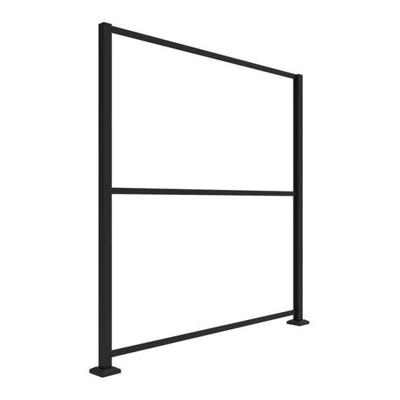
3x6' DECORATIVE SCREEN PANEL
FRAME KIT ASSEMBLY INSTRUCTIONS
Warning
• Read all instructions before installing the product.
• When using tools, refer to the manufacturer's safety instructions.
• Make sure the posts will be held in place by a sturdy structure and
reinforce the surface it stands on as necessary.
• Improper product installation can cause injury. Always wear safety
glasses when cutting, drilling and assembling the product.
• Improper installation may cause product damage or injury to the
person performing the installation.
• Check the local building code to determine if the product meets the
pool fencing requirements.
NOTE
• DO NOT assemble the product if there are missing or damaged parts.
• DO NOT return the product to the store. For help or replacement
parts, call 1‐800‐336‐2383.
Before You Begin: This product is intended for decorative
use only. It is the responsibility of the installer to meet
and/or exceed all code and safety requirements and to obtain
required building code permits as necessary.
Kit contains:
‐ (2) 2" Aluminum End Posts
‐ (2) Top/Bottom U‐Channels (Rail)
‐ (1) Mid H‐Channel (Rail)
‐ Surface Mount Kit
‐ (2) Post Caps
‐ Hardware (Screw kit)
‐ #2 square drive drill bit
‐ #3 Phillips drive drill bit
‐ 1/8" Metal Drill Bit
Required, Sold Separately:
‐ (2) 3x6 Decorative Screen Panels
‐ 3/8" Bolts/Screws for mounting base plates to a structure
Optional to Connect Frame Kits, Sold Separately:
‐ Line Post Extension Kits #73045673
‐ Corner Post Extension Kits #73045674
Tools Needed:
‐ Drill
‐ Pencil
‐ Tape Measure
‐ Rubber Mallet
‐ 3" Spacer Blocks
‐ 1/8" Metal Drill Bit
Step 1
Determine where you would like to install the frame kit. Make
sure the posts will be held in place by a solid structure and if
necessary reinforce the surface it stands on. Then, lay posts
down flush on a flat surface or table.
Step 2
Install base plates to bottom of posts. Locate bottom post with
pre‐tapped holes and attach the bottom plate to that end.
Using only the #3 Phillips drive drill bit provided in surface
mount kit, screw base plate to bottom of post through the 4
screw bosses. Drill should be set to low speed when securing
plates to post.
Step 3
Set first post in desired location. Ensure mounting surface has
proper structure to hold post before fastening in place. Use
the post assembly to mark the holes for the surface mounting
plate. Mark and drill holes for appropriate 3/8" fasteners
(fasteners will vary depending on mounting surface).
Advertisement

Related Manuals for Barrette 73045673

Summary of Contents for Barrette 73045673
- Page 1 Required, Sold Separately: Step 2 ‐ (2) 3x6 Decorative Screen Panels Install base plates to bottom of posts. Locate bottom post with ‐ 3/8” Bolts/Screws for mounting base plates to a structure pre‐tapped holes and attach the bottom plate to that end. Using only the #3 Phillips drive drill bit provided in surface Optional to Connect Frame Kits, Sold Separately: mount kit, screw base plate to bottom of post through the 4 ‐ Line Post Extension Kits #73045673 screw bosses. Drill should be set to low speed when securing ‐ Corner Post Extension Kits #73045674 plates to post. 3x6’ DECORATIVE SCREEN PANEL FRAME KIT ASSEMBLY INSTRUCTIONS Warning • Read all instructions before installing the product. • When using tools, refer to the manufacturer’s safety instructions. • Make sure the posts will be held in place by a sturdy structure and reinforce the surface it stands on as necessary. • Improper product installation can cause injury. Always wear safety glasses when cutting, drilling and assembling the product. • Improper installation may cause product damage or injury to the person performing the installation. • Check the local building code to determine if the product meets the Tools Needed: pool fencing requirements. ‐ Drill NOTE ‐ Pencil • DO NOT assemble the product if there are missing or damaged parts. ‐ Tape Measure ...
- Page 2 Step 4 Step 6 Step 7 Place two 3" spacer blocks to support bottom rail. Take bottom Locate where to pre‐drill Once screws are secure in both rail and insert into channel or first post, resting on the 3" spacer a hole through post and posts, slide decorative screen blocks. Note: This step is to set distance in between posts. rail as shown below. panel in‐between posts in Pilot holes for screws grooves from top until it rests in should be located the bottom U‐Channel. directly on the intersection of small Step 8 groove of the post and Slide H‐Channel in the groove from the top, resting it on the channels. Be sure not to top of the Decorative Screen Panel. Lift H‐Channel up 1/8" (to drill all the way through allow for expansion and contraction), then pre‐drill a hole the back side of the post. following same process in step 6. Screw should be installed directly on the small groove of the post, connecting with the H‐ Channel. Line Post Shown. Be sure not to drill all the way through the back side of post. Step 5 MUST pre‐drill through this surface. Take second post and insert opposite side of bottom rail into ...
- Page 3 ‐ Vis/boulons de 3/8 po pour Phillips #3 fourni dans l'ensemble de montage, visser la plaque plaque de montage sur une au bas du poteau au travers des 4 marques de vis. La perceuse structure doit être ajustée sur une vitesse lente lors du vissage de la INSTRUCTIONS D’ASSEMBLAGE POUR plaque au poteau. Optionnel, pour ajouter des JEU DE STRUCTURE POUR PANNEAUX 3x6’ ensembles de cadres vendus séparément : ‐ Jeu d’extension de structure Avertissement pour installation en ligne #73045673 • Lire toutes les instructions avant l’installation du produit. ‐ Jeu d’extension de structure • Lors d’utilisation d’outils, se référer aux instructions de sécurité du pour installation en coin manufacturier. #73045674 • S’assurer d’avoir une prise solide et si nécessaire, solidifier la structure au sol. • Une mauvaise installation du produit peut causer des blessures. Toujours porter des lunettes de sécurité lors de la coupe, du perçage et de l’assemblage du produit. Outils nécessaires : • Une installation incorrecte est susceptible de causer des dommages au ‐ Perceuse produit ou des blessures à la personne qui fait l’installation. ‐ Crayon ...
- Page 4 Étape 7 : Étape 4 : Étape 6 : Une fois que les vis sont bien fixées dans les Placer les deux blocs d'espacement de 3 po afin de supporter la Vérifier l’emplacement pour le deux poteaux, faire glisser le panneau traverse inférieure. Prendre la traverse inférieure, la glisser dans la pré‐perçage du trou au travers décoratif entre les poteaux dans les rainure du premier poteau et la déposer sur les blocs du poteau et de la traverse tel rainures du haut jusqu'à ce qu'il repose d'espacements. Remarque : cette étape sert à définir la distance que montré ci‐dessous. Les dans la moulure inférieure en U. entre les poteaux. trous pilotes devraient être Conseil: S'assurer que les panneaux sont localisés directement sur placés dans la direction désirée avant le l’intersection de la petite montage. rainure du poteau et celle de la traverse en prenant soin de ne Étape 8 : pas transpercer la face opposée Glisser la moulure en H dans la rainure à partir du haut, du poteau. la déposant sur le dessus du panneau décoratif. Soulever la moulure en H de 1/8 po pour permettre l'expansion et Poteau de fin montré. S’assurer de la contraction, puis pré‐percer un trou en suivant le ne pas transpercer la face opposée même procédé qu’à l’étape 6. La vis doit être installée du poteau. directement sur la petite rainure du poteau, en raccord ...