Advertisement
The UTP cab bus panel provides a low cost means of adding
walk around capability to your layout.
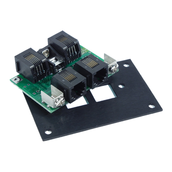
A front panel plate and two #6 screws for attaching it to the UTP
printed circuit board are supplied. Note that if you want the LED
at the top of the panel you should install the UTP "upside
down". This will also keep dust from building on (and inside)
the RJ-12 connectors
The panel has 4 RJ-12 connectors wired in parallel, two on the
front and two on the rear. Your cab bus can be "daisy chained"
from one panel to the next using the rear connectors. One or
two cabs can then be plugged in to the front connectors. Please
note the "Command Station" side versus the "More UTP
panels" side in the figure below when wiring your panels.
COMMAND
STATION
MORE UTP
PANELS
Warning: This product contains chemicals known
to the State of California to cause cancer, birth
defects, or other reproductive harm
Cab Bus Fascia Panel
Model # UTP
NCE Corporation
82 E Main Street
Webster, NY 14580
Advertisement
Table of Contents

Summary of Contents for NCE UTP
- Page 1 A front panel plate and two #6 screws for attaching it to the UTP printed circuit board are supplied. Note that if you want the LED Cab Bus Fascia Panel at the top of the panel you should install the UTP “upside...
- Page 2 A front panel plate and two #6 screws for attaching it to the UTP printed circuit board are supplied. Note that if you want the LED at the top of the panel you should install the UTP “upside Cab Bus Fascia Panel down”.
- Page 3 30-40 foot intervals. This is easily done by plugging a 12-14VDC power supply in to the 5.5/2.5mm jack on the back of the UTP. The center pin is positive (+) and the sleeve is negative. We recommend the NCE P114 (p/n 5240221) or other power supply in the range of 12 to 14 volts DC with a capability of at least ½...
- Page 4 30-40 foot intervals. This is easily done by plugging a 12-14VDC power supply in to the 5.5/2.5mm jack on the back of the UTP. The center pin is positive (+) and the sleeve is negative. We recommend the NCE P114 (p/n 5240221) or other power supply in the range of 12 to 14 volts DC with a capability of at least ½...
Need help?
Do you have a question about the UTP and is the answer not in the manual?
Questions and answers