Advertisement
Quick Links
Modbus TCP Server/DeviceNet Master
1. Introduction
This manual introduces the user to the methods used to implement the
GW-7434D module into their applications in a quick and easy way. This will only
provide with the basic instructions. For more detailed information, please refer to
the GW-7434D user manual located on the ICPDAS CD-ROM or download it
from the ICPDAS web site:
CAN_CD:\DeviceNet\Gateway\GW-7434D\Manual
http://www.icpdas.com/products/Remote_IO/can_bus/GW-7434D.htm
The goal of this manual is focused on helping users to quickly familiarize
themselves with the GW-7434D module. Here, we use one GW-7434D and two
DeviceNet devices as the example that will demonstrate how to use the
GW-7434D modules. The architecture of this example is depicted below.
After configuring and letting the GW-7434D start to communicate with these two
GW-7434D Quick Start User Guide (Version 2.0, Aug/2010)
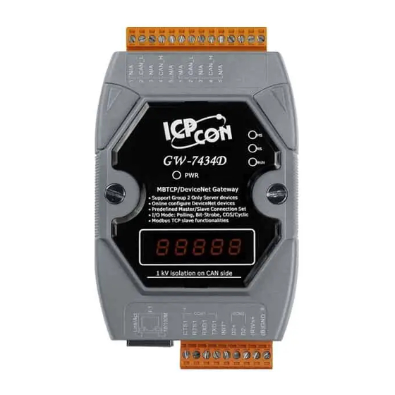
GW-7434D
Gateway
Quick Start User Guide
or
1
Advertisement

Subscribe to Our Youtube Channel
Summary of Contents for ICP CON GW-7434D
- Page 1 1. Introduction This manual introduces the user to the methods used to implement the GW-7434D module into their applications in a quick and easy way. This will only provide with the basic instructions. For more detailed information, please refer to...
-
Page 2: Hardware Installation
Step2: Connect the (R)Vs+ and (B)GND pins of the GW-7434D module to the DC power supply (10~30V Step3: Connect the Ethernet ports of the GW-7434D and the PC to the hub with standard network cable respectively. Step4: Connect the CAN ports of the GW-7434D with these two DeviceNet devices GW-7434D Quick Start User Guide (Version 2.0, Aug/2010) - Page 3 “Configuration Wizard” and “GW-7434D Utility” tools. The details of this procedure are shown below. For more information about setting steps, please refer to section 5 of the GW-7434D’s user’s manual. Step1: Configure the network parameters via “Configuration Wizard”...
- Page 4 ID then press OK button Step5: Now users need to configure the connection parameters between the GW-7434D and these two parameters by double click the left of mouse button on the device’s picture. GW-7434D Quick Start User Guide (Version 2.0, Aug/2010)
- Page 5 Step6: After configuring these two devices, the GW-7434D will start to communicate with two devices. And the Utility will start to monitor the status of the GW-7434D. Step7: Finally, users need to map these two devices’ IO connection data path into GW-7434D’s Input/Output Data Area.
- Page 6 Step 8: After clicking “Save setting”, the GW-7434D Utility generates one record file (default file is called MBTCPDNM.ini). You can run the GW-7434D Utility to load the record file to review all settings of specific GW-7434D. If you forget to store these settings, you can still obtain the information for the GW-7434D via Ethernet.
- Page 7 Then users can get/set the IO data of these two devices by the Utility tool. Or users can get/set the IO data of these devices via using Modbus TCP function code 4 and 16 commands to set/get data to/from GW-7434D’s IO Data Area, The details of this procedure are shown below.
- Page 8 0100~0115 after click the “Get Data” button or “Auto button”. Step3 By pressing the “Set Data” button, users also can set the data on the Output Memory Table into GW-7434D’s output data area. GW-7434D Quick Start User Guide (Version 2.0, Aug/2010)
- Page 9 Users can get /set these two devices data by using Modbus/TCP function code 4 and 16 commands to set/get data to/from GW-7434D’s IO Data Area. The following tables are the setting of the address mapping on the section 3, step7.
- Page 10 Step2: Using Modbus/TCP function code 16, force multiple registers, to write output data into GW-7434D’s Output Data Area. Output Data of Device_1 Response: Setting OK Output Data Function code 16, force of Device_2 multiple registers GW-7434D Quick Start User Guide (Version 2.0, Aug/2010)
Need help?
Do you have a question about the GW-7434D and is the answer not in the manual?
Questions and answers