Table of Contents
Advertisement
Quick Links
Advertisement
Table of Contents

Summary of Contents for ETS ETS.A
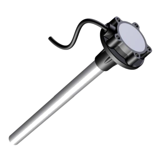
- Page 1 Fuel Level Sensor ETS.A Operating Manual...
-
Page 2: Table Of Contents
Connection ..................... Error! Bookmark not defined. Installation Sequence ..........................13 End Cap ............................... 14 Calibration ................................15 Calibration using the Universal Service Adapter ..................16 Troubleshooting..............................19 Marking Code......................Error! Bookmark not defined. Transport and Storage ............................23 Manufacturer Distributor www.ets-by.by www.metrotec.ee... -
Page 3: Purpose
1 Purpose The analogue fuel level sensor ETS.A (below, also ‘sensor’) is intended for measuring changes in the level of liquid fuels and lubricants (LFL) and may be used in vehicles and LFL storage terminals as a component of systems measuring and controlling the volume of LFL such as various types of petrol, diesel and lubricant oils. -
Page 4: Technical Parameters
**Additional limiting error accounts for the effect of the temperature of ambient air in the range of – 40 °C …+70 °C 3 Package Contents Item Name Quantity The sensor ETS.A Extension cable Gasket Operating manual (incl. ratings sheet, warranty coupon) - Page 5 In turn, this may render the sensor non-functional. For operating range values of supply voltage, see the section Technical Parameters. Manufacturer Distributor www.ets-by.by www.metrotec.ee...
-
Page 6: Installation And Operation
In case of installation to the vehicle’s native fuel level sensor’s inlet an adapter, available from the manufacturer as an accessory, must also be installed and connected (Fig. 4, see Operating Manual for USA.ETS Light 3.0) because the sensor is not equipped for a direct connection to the fuel level gauge on the vehicle’s native instrument panel. -
Page 7: Connection
IMPORTANT NOTE: Where the readings of several sensors are to be combined, frequency-based sensors (Fuel Level Sensor ETS.F, available from the manufacturer) must be used, the output signal of the summator being a voltage in the range of 0…10 V. - Page 8 Supply ground wire (–) connects to sensor body (resistance between ground wire and the body is < 1 Ω). Version 2: Sensor with carbon plastic body. Rated for direct connection to the vehicle’s battery or onboard network. Manufacturer Distributor www.ets-by.by www.metrotec.ee...
- Page 9 Legend Manufacturer Distributor www.ets-by.by www.metrotec.ee...
- Page 10 The connection to B is made on the vehicle’s chassis under the instrument panel. IMPORTANT NOTE: Ground wires to the sensor and to the monitoring terminal should be run from the same point. Advantages: ✓ Reliability ✓ Simplicity Disadvantages: ✓ Does not allow uninterrupted monitoring of fuel level Manufacturer Distributor www.ets-by.by www.metrotec.ee...
- Page 11 ✓ Poor reliability, unless protected 100% from contact between the sensing assembly’s outer tube and the tank body or the sensing assembly’s outer tube and the native fuel level sensor. ✓ Cannot be used on fuel tanks of petrol-engine vehicles. Manufacturer Distributor www.ets-by.by www.metrotec.ee...
- Page 12 NOTE: Points А and B are connected respectively to the power (+) and ground (−) terminals of the battery. Advantages: ✓ Reliability: DC/DC solution protects both the sensor and the monitoring terminal ✓ Ensures round-the-clock monitoring Disadvantages: ✓ Cost Manufacturer Distributor www.ets-by.by www.metrotec.ee...
-
Page 13: Installation Sequence
3. Plug the end cap supplied with the sensor into the cut end (see section 5.5 for information on the cap). IMPORTANT NOTE: DO NOT use the sensor without the end cap – this may result in damage to the sensor due to loosening of the tubes during use! Manufacturer Distributor www.ets-by.by www.metrotec.ee... -
Page 14: End Cap
After insertion in the sensor’s end, the cap must be seated in place by pushing the rod in until it is flush with the cap. This expands the cap’s wings and wedges it in the sensor centre tube (Fig. 13). Figure 13. End Cap in Position 2 Manufacturer Distributor www.ets-by.by www.metrotec.ee... -
Page 15: Calibration
IMPORTANT NOTE: The calibration process may be run also with an uncut sensor in order to extend the drop range of its output voltage. IMPORTANT NOTE: If the sensor has been immersed in fuel, it must be allowed to drain for at least 5 minutes before starting calibration. Manufacturer Distributor www.ets-by.by www.metrotec.ee... -
Page 16: Calibration Using The Universal Service Adapter
Figure 15. Connecting the Sensor to PC To connect the sensor to a PC, use the Universal Service Adapter ETS.USA 2.2 (Fig. 16) available from the manufacturer. A 3-pin cable (USA–ETS.F_A, supplied with the adapter) is required to connect the adapter to the sensor and to calibrate the sensor. - Page 17 When the sensor has been successfully connected, the application will indicate the connection (the main window of the application will display the notification message Connection: on) (Fig. 20). Figure 20. Connecting the Sensor 8. Connect probe to the sensor’s centre electrode. IMPORTANT NOTE: DO NOT touch the electrode! Manufacturer Distributor www.ets-by.by www.metrotec.ee...
- Page 18 IMPORTANT NOTE: Should an error arise during calibration, repeat the process anew. As a result of calibration, the voltage provided by the sensor will be 0 V when dry and approximately 9.8 V when completely filled with fuel. Manufacturer Distributor www.ets-by.by www.metrotec.ee...
- Page 19 Figure 24. Voltage of Sensor When Dry Manufacturer Distributor www.ets-by.by www.metrotec.ee...
-
Page 20: Troubleshooting
Cause: the sensor has been cut by more than 10% (for non-cuttable sensors), or by more than 60% (for cuttable sensors). The sensor has been incorrectly calibrated. Damage to the sensor’s electrodes. Manufacturer Distributor www.ets-by.by www.metrotec.ee... - Page 21 Cause: the composition of the liquid measured differs from that of diesel or petrol. Periodic shorting of the measuring element in the tank by water or other impurities. The sensor has been incorrectly calibrated. Manufacturer Distributor www.ets-by.by www.metrotec.ee...
-
Page 22: Marking Code
16 sec Each sensor is diestamped by the interrupted dot method with a 10-digit code marking: Symbol Meaning Type of ETS.A Length Code Device Code Date 4 5 6 7 8 9 10 Sequential number of code digit... -
Page 23: Transport And Storage
−40 °C…+80 °C; • relative humidity at 40 °C: < 95%. 10 Distributor contatcs Metrotec LLC Haljas tee 25, 12012 Tallinn Tel. +372 6274730 E-mail: info@metrotec.ee http://www.metrotec.ee We will be happy to answer Your questions Manufacturer Distributor www.ets-by.by www.metrotec.ee... - Page 24 Manufacturer Distributor www.ets-by.by www.metrotec.ee...
Need help?
Do you have a question about the ETS.A and is the answer not in the manual?
Questions and answers