Advertisement
Quick Links
Advertisement

Related Manuals for Trueful Electronics C3V Series

Summary of Contents for Trueful Electronics C3V Series
- Page 1 C³V Series 2010 4005 6003 Programmable DC Power Supply...
- Page 2 1. Important Safety Instructions --------------------------------------- p. 4 1.1 General 1.2 Symbols & Messages 1.3 Safety Instructions 1.3.1 Transportation 1.3.2 Ambient Conditions 1.3.3 Installation 1.3.4 Operation 1.3.5 Service & Maintenance 1.3.6 Storage 2. Get Acquainted with the C³V ----------------------------------------- p. 7 2.1 Front Panel Overview 2.2 Models &...
- Page 3 6. C³V Series Communication Protocol ----------------------------- p. 17 6.1 Communication between PC and C³V Series 6.2 Message Terminator of Protocol: CR LF 6.3 Data Format (PC to C³V Series) 6.3.1 ADDR (PC to C³V Series) 7. Automatic Fan Speed vs Temperature Control --------------- p. 23 7.1 PWM Fan Speed Control 7.2 Over Temperature Protection (OTP) Alarm 8.
-
Page 4: Important Safety Instructions
1. Important Safety Instructions 1.1 General This chapter contains important safety instructions for fully utilizing the C V Series DC Power Supply. It is important that this manual is read and understood by all persons prior to transporting, installing, operating, servicing, or maintaining the product. 1.2 Symbols &... - Page 5 1.3.2 Ambient Conditions The product is designed for indoor use. Condensation may occur after the product was shipped, or subject to a sudden change in an atmosphere of temperature or humidity. Do not use the product for at least two hours to ensure it is dry before turning it on.
- Page 6 1.3.5 Service & Maintenance The product operates at hazardous high voltage (near DC 380V or AC 267V). Only qualified personnel can carry out servicing or maintenance. Always use a properly rated voltage sensing device to confirm that all power is off. Before attempting any service, disconnect the product from all power supply and ensure that no harmful residual voltage remains at the terminals of bulk capacitors.
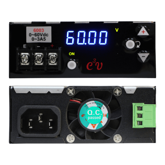
- Page 7 2. Get Acquainted with C³V Series 2.1 Front Panel Overview Panel display: 4-digit meter displays voltage, current and internal Display Meter temperature of the product. For auxiliary uses of system parameters setup. Output key Turns the output on/off. Enter key Circulatory mode selection.
- Page 8 Green “ON” symbol. Output LED Off: Output Off. Lit: Output On. Ground terminal, negative terminal, and positive Output terminals terminal, respectively. Model & output See 2.2 ratings 2.2 Models & Output Ratings C³V series consists of 3 models and ratings as listed below: Model 2010 4005...
-
Page 9: Operation
3. Operation 3.1 General C³V Series integrates two power supplies – constant voltage (CV) and constant current (CC). These two power supplies exclusively operate, and outputs do not exceed user-preset limit. CV or CC states are dependent on and limited by the comparison between load conditions and C³V Series settings. - Page 10 Setting Mode By pressing the Enter key for 3 seconds, you will hear a short beeping sound. This indicates that the C³V Series has entered “Setting Mode”. “The V-LED OR A-LED “ AND “ the respective decimal point ” will be blinking on the 4-digit Display Meter. Use the Up or Down keys to set the desired voltage or current.
- Page 11 3.4 Switching between Two Modes Press the Enter key for 3 seconds to switch between Output (Reading) Mode and Setting Mode. This operation is especially useful for circuit experiments where frequent changes of V or A is necessary. P.11...
- Page 12 4. Keys: Special Functions Some keys are programmed with special functions. 4.1 Normal Operations Press to toggle the output on / off (refer to 4.3 for default Output key AC power setting). Press for 3 seconds to select between Output (Reading) Mode and Setting Mode.
- Page 13 4.3 Default Output State (ON / OFF) Output state when the unit is powered on: JP7 on MCU card Default state at AC power on OPEN Output OFF SHORT Output ON Note: User modification not recommended. P.13...
- Page 14 5. C³V Series Communication Interfaces C³V Series provides three isolated communication interfaces: RS232, USB and RS485.The selected interface must be confirmed before shipping and cannot be modified after delivery. 5.1 Communication Data Rate Data rate: 57600/N/8/1 ■ Baud Rate: 57600 ■...
- Page 15 SGND Signal Ground Data Set Ready Input Request To Send Output Clear To Send Input Ring Indicator Input 5.2.1 RS232 Connection with PC 5.3 C³V Series with USB Interface USB Type B Connector as shown below: 5.4 C³V Series with RS485 Interface The RS485 address needs to be set up before communication.
- Page 16 5.4.1 RS485 Termination Resistor (120R) Installation & Wiring When installing, please connect a 120 Ω termination resistor to the “+/-“ terminals of the green terminal block of the final parallel unit of C³V Series. 5.4.2 RS485 Address The RS485 address must be set from 1 to 32 and cannot duplicated. USB & RS232 interface do not require set up as default value “0”...
- Page 17 6. C³V Series Communication Protocol Commands can be written in either ASCII or hexadecimal codes. C³V Series never sends messages till it receives the CMD from the PC. 6.1 Communication between PC and C³V Series As shown below: PC sends “CMD-L” – C³V Series replies “Status-L” ...
- Page 18 6.2 Message Terminator of Protocol: CR LF CR = 0x0D (HEX) LF = 0x0A(HEX) 6.3 Data format (PC to C³V) 6.3.1 ADDR (PC to C³V Series) This field is the address code of the protocol. If this code is correct, C³V Series will receive commands. Every C³V Series unit can be set with an address from 1 to 32.
-
Page 19: Function Description
When the C³V Series receives and C³V01 decodes the code (address), it will execute the received command. RS485 (multiple units) C³V02 . ……….. C³V32 ……….. Command Set (PC to C³V Series) This field is the command code of the protocol. Function Description The L query returns all C³V Series statuses: Reply: Status-L... - Page 20 ON turns the output on: Reply: Status-OK C³V00 ON<CR><LF> OK<CR><LF> OFF turns the output off: Replay: Status-OK C³V00 OFF<CR><LF> OK<CR><LF> Data Format CMD-L (C³V Series to PC) Status-L (C³V Series to PC) This field is the command code of this protocol. Status Function Description Reply voltage value of setting:...
- Page 21 Reply output voltage value: C³V00 L<CR><LF> Vout Vcom=20.00,Vout=1.35,Icom=3.500,Iout=0.000,Tspace=30.8,Relay=ON <CR><LF> Reply current limit setting: C³V00 L<CR><LF> Icom Vcom=20.00,Vout=1.35,Icom=3.500,Iout=0.000,Tspace=30.8,Relay=ON <CR><LF> Reply output current value: C³V00 L<CR><LF> Iout Vcom=20.00,Vout=1.35,Icom=3.500,Iout=0.000,Tspace=30.8,Relay=ON <CR><LF> Reply RELAY status: C³V00 L<CR><LF> Relay Vcom=20.00,Vout=1.35,Icom=3.500,Iout=0.000,Tspace=30.8,Relay=ON <CR><LF> Reply heat sink temperature value: C³V00 L<CR><LF>...
- Page 22 Status-OK (C³V Series to PC) Status-OK Function Description Reply OK C³V00 ON P.22...
- Page 23 7. Automatic Fan Speed vs Temperature Control 7.1 PWM Fan Speed Control C³V Series uses PWM to control the fan speed and temperature. The MCU senses the internal temperature of the unit and adjusts the fan speed automatically. This extends the fan lifespan and reduces mechanical noise when there is no output. If the output current exceeds one half of the maximum current, the fan will be set at full speed automatically.
- Page 24 8. C³V Series Wiring and Connections 8.1 All Connections The following table shows the types of connection to the unit: 1. AC input 2. DC output 3. Communication interfaces. Please refer to the last graphic in this chapter. To be connected and fixed Connection with external at C³V cables...
- Page 25 8.2 Special Connectors to Prepare “O” or “Y” type terminal 8.3 Wire Size Table The following table suggests some applicable sizes for DC output lead wire where the maximum current and minimum DC resistance are considered. Diameter Rated Current Gauge Ω/meter (mm) AWG #12...
- Page 26 8.4 Types of Panel Layout The following table and graphic illustrate the types of input / output connection and communication interfaces on panels. Terminal board output USB type B interface Banana socket output RS-485 interface IEC AC input w/o Terminal board AC input interface and RS-232 interface P.26...
-
Page 27: Mounting And Ventilation
9. Mounting and Ventilation We suggest flat mount or erect mount when installation the C³V Series. Note that both mounting methods require clear ventilation paths. Please keep the ventilation paths free of blockings and obstacles. 9.1 Flat Mount Illustration for the flat mount and the associated ventilation flows Position reference for flat mounting Caution: Using a screw longer than 5mm may penetrate the circuit board and cause product failure. - Page 28 9.2 Erect Mount Illustration for the erect mount and the associated ventilation flows. Positioning reference for erect mounting. Caution: Using a screw longer than 7mm may penetrate the circuit board and cause product failure. P.28...
- Page 29 10. C³V Series Specifications C³V Series 2010 4005 6003 ELECTRIC AC input rating Power 210W max. Voltage 85~264VAC Current 2.4A max./115VAC , 1.2A max./230VAC Frequency 47~63Hz Inrush 22A max./115VAC , 46A max./230VAC power factor PF>0.95/230VAC , PF>0.99/115VAC ELECTRONIC DC output rating Voltage, Volt 0-20V 0-40V...
- Page 30 C³V Series 2010 4005 6003 Measurement resolution Voltage, mV 10mV 10mV 20mV Current, mA Measurement accuracy Voltage, % 0.05 % +5 cnt 0.05 % +6 cnt 0.05 % +7 cnt Current, % 0.2% + 10 cnt 0.1% +8 cnt 0.1% +8 cnt Temperature coefficient Voltage 0.001%/ ℃...
-
Page 31: For Example
11. Appendix: Ordering and options details: Neutral format of order code is shown as follows: C3V-vvii-FT-RT-C Options in details: vvii : output ratings FT: Front DC output terminals RT: Rear AC input connections 2010: 0~20V, 0~10A TB: terminal board TB: terminal board 4005: 0~40V, 0~5A BN: banana jack EC: IEC male...
Need help?
Do you have a question about the C3V Series and is the answer not in the manual?
Questions and answers