Table of Contents

Subscribe to Our Youtube Channel
Related Manuals for Lofrans 636305


Summary of Contents for Lofrans 636305
- Page 1 MINI RADIO REMOTE CONTROL INSTALLATION OPERATION MAINTENANCE USER MANUAL THIS MANUAL MUST BE KEPT ON BOARD AT ALL TIMES Via Philips 5, 20900 Monza (MI), Italy Tel: +39 039 2001973-936 - Fax: +39 039 2004299 Email: contact@lofrans.com - www.lofrans.com...
-
Page 2: Table Of Contents
Contents Section Title Page DESCRIPTION TECHNICAL SPECIFICATIONS PRODUCT REFERENCES PACKAGING CONTENTS GENERAL DIMENSIONS INSTALLATION AND CONNECTIONS SET UP INSTRUCTIONS RESSETING ADDING EXTRA TRANSMITTERS WIRING EXAMPLES REPLACING THE BATTERIES TROUBLESHOOTING PRECAUTIONS WORLDWIDE DISTRIBUTION WARRANTY It is strongly advised that only qualified marine electricians should install this equipment. For any boat requiring official classification, bodies of approval should also be consulted at the earliest opportunity. -
Page 3: Description
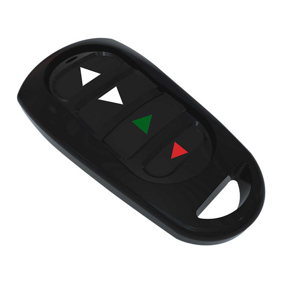
1- DESCRIPTION The Lofrans’ mini radio remote control is designed to work with Lofrans’ and Max Power’s entire product lines. The mini remote control can also be used to operate any other onboard equipment for which it may be useful. - Page 4 Federal Communication Commission Interference Statement This equipment has been tested and found to comply with the limits for a Class B digital device, pursuant to Part 15 of the FCC Rules. These limits are designed to provide reasonable protection against harmful interference in a residential installation. This equipment generates, uses and can radiate radio frequency energy and, if not installed and used in accordance with the instructions, may cause harmful interference to radio communications.
-
Page 5: Product References
The Remote Control packaging includes: 636305 (EU/US) MINI REMOTE CONTROL 9 1 Transmitter 9 1 Receiver 9 1 String 9 1 User manual 9 Dual lock tape *Transmitters are available as individual spare parts. Please contact Lofrans’ customer support at www.lofrans.com for any assistance... -
Page 6: General Dimensions
5- GENERAL DIMENSIONS 17,7 100,5 All dimensions are in mm 6- INSTALLATION AND CONNECTIONS 1. Turn OFF the power supply to the thruster or the equipment being connected. 2. Fit the receiver in a dry and accessible area (preferably not in the bilge). For mounting, use the dual lock tape provided. -
Page 7: Set Up Instructions
CAUTION: Fit the receiver as far as possible from large metallic objects, electric motors or high current cables. Please connect the radio receiver’s power supply to the yacht’s main service battery bank. The battery pack powering the receiver must be sufficiently charged (refer to the battery supplier’s recommendations). - Page 8 Figure A Figure B Setting of Working Modes: 1. Momentary Mode: Pressing the learning key button on the receiver board once (fig.A) and the LED indicator on receiver board will signaling simultaneously. Then press any of the remote control button (fig.B) as a result the LED on the control board flashes 3 times in succession meaning that the setting of the Momentary Mode is successfully.
- Page 9 button, the first output is off and the second output is activated, the relay of which remains on and so on. 4. 2CH Momentary + 2CH Toggle: Pressing the learning key button on the receiver board four times (fig.A) and the LED indicator on receiver board will signaling simultaneously.
-
Page 10: Adding Extra Transmitters
In case of error or doubt concerning the configuration, clear the receiver’s memory (Chapter 8) and start from the beginning. This will require the reconfiguration of all remote controls. * Receivers and transmitters are available as individual spare parts. Please contact Lofrans’ customer support at www.lofrans.com for any assistance. - Page 11 • “ COM” terminals stand for Common In the corresponding terminal, connect the voltage supply for the corresponding load The table below with the matching figure shows the correspondence of the mini remote control buttons with the corresponding outputs on the receiver. 1 DC 12V Positive power supply input (V+) 2 Negative power supply input (V-) 3 Channel D - Normal Closed of relay (NC) 4 Channel D - Common of relay (COM)
- Page 12 Example 1 (fig.1) A thruster and a windlass need to be operated through the mini remote. The logic of the configuration is that a product operates when the circuit is closed. In such a case, the machine should be wired into the “NO” terminals because the machine operates when the button of the mini remote is pressed.
-
Page 13: Replacing The Batteries
Example 3 (fig.3) Two products with inverse logic are needed to be operated from the mini remote control. The product should always operate, and by the pressing the appropriate button should make the corresponding output stop working. The voltage supply for operating the load should be connected at the common terminal. -
Page 14: Troubleshooting
12- TROUBLE SHOOTING Before contacting Lofrans, please consult the following trouble shooting guide. Problem Check The receiver’s LED doesn’t light up Check the power supply of the receiver The transmitter’s LEDs do not light up Check the transmitter’s battery and the polarity Check the connections of the receiver’s relay... -
Page 15: Warranty
15- WARRANTY Warranty coverage The equipment is guaranteed to be free of manufacturing and operation defects under normal usage conditions for a period of 2 years from the date of purchase by the end user (upon production of sales receipt or other proof of purchase). This warranty is transferable to subsequent owners of this equipment during the period of coverage. - Page 16 Examples given for: • Max Power Bow Thruster CT60/CT80 • Max Power Stern Thruster CT60/CT80 • Lofrans Windlass (3 terminals motor) For other makes and models of equipment please refer to the manufacturer’s wiring diagram CONTROL BOX AND REMOTE CONTROL RECEIVER SUPPLY:...
- Page 18 Via Philips 5, 20900 Monza (MI), Italy Tel: +39 039 2001973-936 - Fax: +39 039 2004299 Email: contact@lofrans.com - www.lofrans.com...
Need help?
Do you have a question about the 636305 and is the answer not in the manual?
Questions and answers