
Subscribe to Our Youtube Channel
Related Manuals for Digitimer D360R-4


Summary of Contents for Digitimer D360R-4
- Page 1 Digitimer D360R-4 Isolated 4-Channel Research Amplifier/Filter OPERATOR’S MANUAL For Research Use Only “ Digitimer” is a registered trademark of Digitimer Limited...
- Page 2 Digitimer Ltd – D360R-4 Operator’s Manual Version 1.0 WARNING For Subject and Operator Safety, this manual should be FULLY read and understood before use of this product Digitimer Ltd. Copyright ©2021...
-
Page 3: Table Of Contents
Digitimer Ltd – D360R-4 Operator’s Manual Version 1.0 Table of Contents Section 1 - General Information ......................7 D360R-4 Intended Usage & Description ..................... 7 Precautions and Warnings ........................8 Operator’s Manual .......................... 8 Risks to Subject Safety ........................8 Defibrillator Warning ........................ - Page 4 Section 3 – Software & Hardware Installation ..................23 Software Installation ......................... 23 Hardware Installation ........................25 Section 4 – Navigating the D360R-4 Control Software ................. 29 Overview ............................29 D360R-4 Control Panel ........................30 Channel Enable/Disable Switches ....................30 Channel Linking ..........................
- Page 5 Digitimer Ltd – D360R-4 Operator’s Manual Version 1.0 Section 5 – Using the D360R-4 Amplifier ....................35 Introduction ............................35 Considerations for Use ........................35 Preparing the D360R-4 for Use ..................... 35 Electrode Selection ........................36 Skin Preparation ..........................36 Electrode Lead Routing .........................
- Page 6 Digitimer Ltd – D360R-4 Operator’s Manual Version 1.0 Product Registration Please take time out to register your new product. Details are included in the Section 1 - General Information You can even do it online at:- www.digitimer.com/register Digitimer Ltd. Copyright ©2021...
-
Page 7: Section 1 - General Information
Users should be able to operate the D360R-4, the controlling software, and any associated instruments correctly before carrying out any human studies. The D360R-4 is NOT approved or intended for use in clinical diagnostic, treatment or life support situations and is NOT a medical device. -
Page 8: Precautions And Warnings
Under no circumstances should the D360R-4 Operator simultaneously touch the D360R-4 main unit and the subject. WARNING - The D360R-4 should not be modified as this may present a safety hazard to the subject. Defibrillator Warning The D360R-4 is NOT classified as defibrillator proof and should not be connected to a subject undergoing defibrillation. -
Page 9: Temperature
As no parts of the D360R-4 are expected to wear out the only limitation to the service life is likely to be the ongoing ability to replace electronic components that may randomly fail and damage sustained during normal use. -
Page 10: Environmental Considerations
, please contact us. Modification Status The green and white serial number label affixed to the rear of each D360R-4 contains the unique serial number of that unit. This serial number should be quoted whenever technical support is requested from Digitimer or one of our representatives. -
Page 11: Optional Accessories
Windows compatible D360R-4 Client Software (supplied on USB Stick). Please note that the USB cable supplied is specifically for use with the D360R-4. USB cables from other suppliers are NOT suitable for use with this amplifier and may result in increased EMC emissions or decreased EMC immunity. -
Page 12: Mains Inlet Fuses
This web address is your point of contact for all questions regarding the D360R-4. The contents of this site are now growing rapidly, so please bookmark it so that you can visit it regularly to check out the new items. -
Page 13: Contact Addresses
2-5-47 Tadao Machida Tokyo 194-0035 Telephone: +81 (0)42-789-6022 Fax: +81 (0)42-789-6195 Germany: HW MedicalProducts Neuberg 1-b D-65193 Wiesbaden Telephone: 0611 185 1944 Fax: 0611 185 1946 Please contact Digitimer for information regarding representation in other countries. Digitimer Ltd. Copyright ©2021... -
Page 14: Specifications
Version 1.0 Specifications Safety The D360R-4 has been designed to meet all of the electrical requirements of IEC 60601-1, ensuring safety in a human research environment. This includes but is not limited to: Input circuit is fully electrically isolated. -
Page 15: Outputs
1 m BNC terminated cable for connection to chosen acquisition interface. Software Supplied D360R-4 Client Software compatible with Windows10 (32/64bit) and above. Physical Size Headstage : 134 x 76 x 39 mm, weight : 255g (approximate) ... -
Page 16: Eu Declaration Of Conformity
Digitimer Ltd – D360R-4 Operator’s Manual Version 1.0 EU Declaration of Conformity Placeholder for DoC Digitimer Ltd. Copyright ©2021... -
Page 17: Warranty Information
Warranty Information Limited Warranty Digitimer Limited warrants to the first purchaser, for a period of one year from the date of purchase, that this Digitimer instrument (hereafter referred to as the “Product”) will be free from defective workmanship and materials, and agrees that it will, at its option, either repair the defect or replace the defective Product or part thereof at no charge to the purchaser for parts and labour. - Page 18 Digitimer Ltd – D360R-4 Operator’s Manual Version 1.0 Digitimer Ltd. Copyright ©2021...
-
Page 19: Section 2 - Hardware Overview
Tour of the Hardware Front Panel Components 1. Power LED (Green) The power LED is illuminated when the D360R-4 is connected to a live power supply and switched on via the rear panel On/Off switch. 2. Error LED (Amber) Normally extinguished, the error LED provides the operator with information that can indicate a fault or communication problem. -
Page 20: Headstage Components
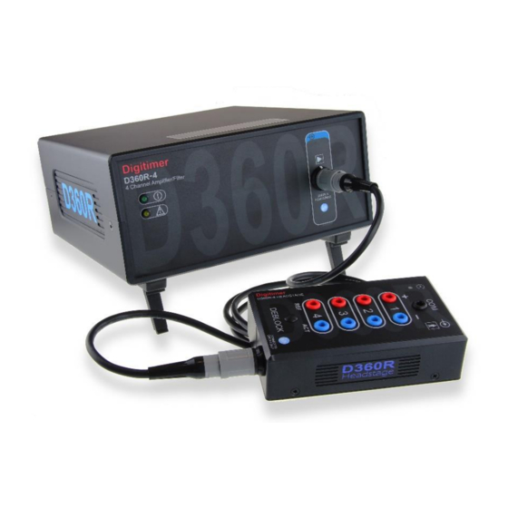
2m long inter-connection cable. Headstage Components 1. Headstage power LED (Green) The power LED is illuminated when the D360R-4 headstage is receiving power from the main amplifier. 2. COMMON (COM) electrode input socket 1.5mm DIN42802 male socket for connection to Common electrode. -
Page 21: Main Amplifier Front Panel & Headstage Printed Symbols
Digitimer Ltd – D360R-4 Operator’s Manual Version 1.0 Main Amplifier Front Panel & Headstage Printed Symbols Main amplifier power indicator Reference electrode connection Caution, consult accompanying Active electrode connection documents. Signal input connection. Common electrode connection Connection to D360R-4 Type BF applied part... -
Page 22: Rear Panel Symbols
Digitimer Ltd – D360R-4 Operator’s Manual Version 1.0 4. Mains Inlet Socket (IEC 60320-C14) For connection to mains socket via supplied mains cable. 5. Mains Fuse Holder Ensure fuses are correct rating for the local voltage supply and match the voltage selector setting. -
Page 23: Section 3 - Software & Hardware Installation
Hardware Installation Software Installation The D360R-4 Client Software provides the virtual front panel for the amplifier, allowing the operator to configure, save and recall amplifier settings and de-block the electrode inputs. The D360R-4 Amplifier will not function correctly until it is connected to a personal computer which is running the D360R-4 Client Software. - Page 24 Digitimer Ltd – D360R-4 Operator’s Manual Version 1.0 Digitimer Ltd. Copyright ©2021...
-
Page 25: Hardware Installation
PC. 1. After ensuring the D360R-4 is set to the correct local voltage and the correct mains fuses are installed and the power switch is set to Off, connect the mains lead (power cord) between a power socket and the mains inlet socket on the D360R-4. - Page 26 5. Once all cable connections have been made, power On the D360R-4 using the switch on the rear panel of the main amplifier. 6. To run the software, locate and click on the D360R-4 entry in the Windows Start Menu or double-click on the desktop shortcut.
- Page 27 Digitimer Ltd – D360R-4 Operator’s Manual Version 1.0 8. Once a D360R-4 is detected and communication with the host PC established, the Control Panel should become populated with the settings of the connected amplifier(s). 9. If the amplifier front panel does not load, check the power/error LEDs, cable connections and try an alternative USB port.
- Page 28 Digitimer Ltd – D360R-4 Operator’s Manual Version 1.0 11. For any unresolved installation problems, please contact Digitimer or our local representative for guidance. Please supply information relating to device serial number, software version and the operating system. Digitimer Ltd. Copyright ©2021...
-
Page 29: Section 4 - Navigating The D360R-4 Control Software
Near the top of the Control Panel, the Device ID (serial number) is given along with the version of the Client Software. Below are the controls for that device. If more than one D360R-4 is connected to the same host PC, each Device ID and settings will be displayed. -
Page 30: D360R-4 Control Panel
Linked channels are hi-lighted by a yellow link icon. Gain Settings The D360R-4 provides the operator with multiple methods for adjusting the amplifier gain and also allows the list of available gains to be customized. The gain of each channel is adjustable from x100 to x3,000,000. -
Page 31: Low Cut Filter Settings
Digitimer Ltd – D360R-4 Operator’s Manual Version 1.0 Clicking on the numerical gain setting value, opens a drop- down list of “favourite” gain options, allowing a specific gain value to be selected more easily. Clicking on the downward pointing arrow located immediately below the Gain header, opens the menu opposite. -
Page 32: High Cut Filter Settings
Notch Filter Settings The D360R-4 has a built in notch filter which is intended for removal of 50Hz or 60Hz mains noise from signals of interest. The notch filter is enabled using a slider switch associated with each channel. -
Page 33: Deblock Control
TTL deblock settings are accessed by clicking on the downward arrow to the right of the deblock icon within the software. Loading and Saving Protocol Settings The D360R-4 allows operators to save and recall amplifier settings which may be assigned to particular recording protocols. -
Page 34: D360R-4 Api Programmer's References
Version 1.0 D360R-4 API Programmer’s References The D360R-4 Client Software includes an API that allows third party software to interface with and control the amplifier settings. Further documentation on this feature will be added to this section in due course. - Page 35 2. The cable connections between the host computer, the D360R-4 and other system components should be checked. 3. The D360R-4 should be switched on at the mains socket and on the rear panel switch. The D360R-4 should be allowed to warm up for one hour before use. This stabilises the internal electronics and ensures drift-free recordings.
- Page 36 Once a study is complete, the subject should be disconnected from the amplifier either by removal of the electrodes or by unplugging the electrode leads from amplifier. The D360R-4 can then be switched off using the rear panel power switch. The D360R-4 Client Software will continue to run until the operator exits from the program according to the instructions in the previous chapter.
- Page 37 Bibliography The D360R-4 is a new product, so at this time we do not have a bibliography for it. Please let us know if you publish any papers using the D360R-4 and if possible please send us a copy. We will be happy to add papers to this list.
- Page 38 Digitimer Limited 37 Hydeway Welwyn Garden City AL7 3BE Web: www.digitimer.com Email: sales@digitimer.com File Reference: N:\Docs\Company\Manuals\D360R-4\D360R-4-MAN_v1.0.docx Updated: 13/08/21...
Need help?
Do you have a question about the D360R-4 and is the answer not in the manual?
Questions and answers