
Summary of Contents for Roper Whitney PEXTO 3416
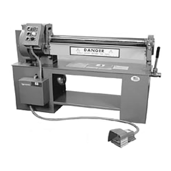
- Page 1 PEXTO No. 3416 No. 3418 ROLL FORMING MACHINES OPERATING INSTRUCTIONS AND PARTS IDENTIFICATION ROPER WHITNEY 2833 HUFFMAN BLVD., ROCKFORD, IL 61103-3990 * 815/962-3011 * FAX 815/962-2227 Website: www.roperwhitney.com Email: info@roperwhitney.com...
-
Page 2: Specifications
Anti-trip footswitch to actuate forming roll rotation, and push button “off” will override for an emergency shutdown. OPTIONAL FEATURES Plain rolls with no grooves. 34 rpm or 45 rpm roll speed. ROPER WHITNEY 2833 HUFFMAN BLVD., ROCKFORD, IL 61103-3990 * 815/962-3011 * FAX 815/962-2227... - Page 3 ROPER WHITNEY COMPANY SAFETY RULES 3416 AND 3418 1. WARNING: Electrical Danger: Misuse or improper installation of machinery connected to a source of electricity may result in accidental shock that could cause injury or death. Installation must conform to National Electric Code (Article 250 - Grounding, etc.) Electrical connections must be made by a trained and qualified electrician.
-
Page 4: Installation
Question - Distributor or Roper Whitney -- Shortages not appearing on the bill of lading or discrepancies between equipment received and the order should be reported to Roper Whitney Corp. immediately. - Page 5 LUBRICATION The specially compounded lubricants or their equivalent as specified on the data plate furnished with your machine and the lubrication chart must be used. See Figure 1 for lubrication points. LUBRICATION CHART LUBRICANT COMPONENT Mobile Texaco INTERVAL BEARING BLOCKS *MOBILE 40 HRS.
- Page 7 CAUTION: DO NOT OPERATE MACHINE WITHOUT PROPER INSTRUCTIONS. Observe all safety rules and regulations. Become familiar with controls and intended operation before using. MACHINE MUST BE SECURELY BOLTED TO FLOOR and connected to correct source of voltage, phase and cycles. WARNING: Electrical danger -- misuse of improper installation of machinery connected to a source of electricity may result in accidental shock that could cause injury or death.
- Page 8 CONTROLS ON-OFF BUTTON --------------- Connects 115 vac to the control when the light goes on. The 115 vac is disconnected when this button is pushed, and the red light goes off. The electric circuit will permit the off button to override the footswitch. FORWARD &...
- Page 9 OPERATION OF THE ROLL BENDER The roll bender machine is designed to initially pinch/grip the sheet material to be formed between the upper roll (not adjustable) and the lower roll (adjustable upward or downward manually by means of adjusting screws located in the housings at each end of the lower roll). The rear (bending) roll is adjustable by means of adjusting screws located in the housings at either end of the rear roll.
- Page 10 Grooves are provided in the right hand end of the lower and rear rolls for forming cylinders with a wired edge. Lubrication and visual inspection at regular intervals are required for good maintenance. Use machine for its intended purpose only and always within rated capacity. Do not operate with guards removed nor when inspection indicates possibility of malfunction.
-
Page 11: Operating Procedure
OPERATING PROCEDURE 1. Select forward rotation by depressing “Forward” button on control panel (see Fig. 6). White light will be illuminated! NOTE: This only determines the direction of rotation the rolls will turn when rotation is actuated by the footswitch. Always select direction of rotation when rolls are not rotating. 2. - Page 13 3416-3418 FORMING MACHINE PARTS LIST REFER TO PARTS IDENTIFICATION CHARTS INDEX PART # DESCRIPTION INDEX PART # DESCRIPTION 767490180 L.H. Housing 767630044 Spacer 267940025 R.H. Housing Assy 767650045 Pivot Screw 767220178 Housing Cover (see below) Upper Roll 767170022 Rocking Box (see below) Lower Roll 767170023...
Need help?
Do you have a question about the PEXTO 3416 and is the answer not in the manual?
Questions and answers