Table of Contents
Advertisement
Quick Links
Advertisement
Table of Contents

Related Manuals for Rosenberg 02CK020-150

Summary of Contents for Rosenberg 02CK020-150
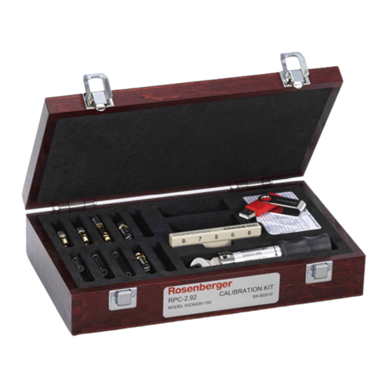
- Page 1 User Manual Calibration Kit 02CK020-150 RPC-2.92 LRL-Version 02CK020-150 (LRL Version) Rosenberger Hochfrequenztechnik GmbH & Co. KG Tel. : +49 8684 18-0 Page P.O.Box 1260 D-84526 Tittmoning Germany www.rosenberger.com Email : info@rosenberger.com 1 / 20...
-
Page 2: Table Of Contents
User Manual Calibration Kit 02CK020-150 RPC-2.92 LRL-Version Contents 1. General Information Calibration Kit Normal Use Warnings Kit Contents Kit Documentation Calibration Certificate 2. Specifications Environmental Requirements Electrical and mechanical Specifications 3. Standard Definitions Standard Definitions Installation of Standard Definitions Standard Definitions file nomenclature 4. -
Page 3: Rpc-2.92
User Manual Calibration Kit 02CK020-150 RPC-2.92 LRL-Version 1. General Information This LRL Calibration Kit does not contain gauges. So all gauge related chapters are only applicable if additional gauges are available, e.g. Rosenberger 02GK0KS-010 or comparable ones. 1.1 Calibration Kit Normal Use Calibration Kits are used as an accessory for Vector Network Analyzers (VNA) to perform vector- error correction. -
Page 4: Kit Contents
User Manual Calibration Kit 02CK020-150 RPC-2.92 LRL-Version 1.3 Kit Contents Table 1-1 Parts of the 02CK020-150 Calibration Kit Device Part number Remarks Quantity 15 mm Air line 02S101-K015 plug/jack 18.3 mm Air line 02S101-K018 plug/jack 40 mm Air line 02S101-K040... -
Page 5: Specifications
User Manual Calibration Kit 02CK020-150 RPC-2.92 LRL-Version 2. Specifications 2.1 Environmental Requirements The electrical performance of vector network analyzers and test port cables are sensitive to ambient temperature drift. Most manufacturers limit the allowable temperature drift to ± 1 K during measurement calibration and during measurements when the network analyser error correction is turned on. -
Page 6: Standard Definitions
User Manual Calibration Kit 02CK020-150 RPC-2.92 LRL-Version 3. Standard Definitions 3.1 Standard Definitions Standard definitions provide the data needed to mathematically describe the electrical characteristics of each calibration standard. Model based standard definitions are the traditional format and can be used on both old and modern VNAs. -
Page 7: Installation Of Standard Definitions
The file extension defines the VNA types the file can be used on. For further Information see the Application Note AN001. KitType (SN)_StdDef_CalDate.Ext • KitType 02CK001-150, 02CK020-150 or customized type • (SN) Serial number (5 character) enclosed by brackets • StdDef ‘mb’... -
Page 8: Vna Calibration
User Manual Calibration Kit 02CK020-150 RPC-2.92 LRL-Version 4. VNA Calibration 4.1 VNA Calibration A VNA is only as useful as the accuracy of the measurements it makes, and this requires the instrument to be calibrated. The calibration process employs a technique called vector error correction, in which error terms are characterized using known standards so that errors can be removed from actual measurements. -
Page 9: Rosenberger Hochfrequenztechnik Gmbh & Co. Kg Tel. : +49 8684
User Manual Calibration Kit 02CK020-150 RPC-2.92 LRL-Version Thru-Reflect-Line The TRL calibration is a special form of the LRL calibration. One line is replaced by a direct thru connection. This simplifies the handling a little bit but limits the upper frequency limit to about 8.9 GHz. - Page 10 User Manual Calibration Kit 02CK020-150 RPC-2.92 LRL-Version 4.3 Other LRL/TRL frequency ranges The above mentioned standard frequency range (1 GHz to 40 GHz) is a combination of two frequency segments: 1 GHz to 5 GHz LRL-Calibration L1 and L3 5 GHz to 40 GHz LRL-Calibration L1 and L2 However, further line combinations are possible to perform LRL/TRL calibrations.
- Page 11 User Manual Calibration Kit 02CK020-150 RPC-2.92 LRL-Version 5. Calibration Kit Service 5.1 Calibration interval Rosenberger suggests a calibration interval of 12 months. Depending on the frequency of use, the wear and the actual requirements a different calibration interval might be suitable. This lies in the responsibility of the user.
- Page 12 User Manual Calibration Kit 02CK020-150 RPC-2.92 LRL-Version 6. Use, Maintenance and Care 6.1 Connector Care It is of particular importance to note that mechanical damage can be inflicted on a connector while making a connection or a disconnection. 6.1.1 Connector Cleaning To ensure a long and reliable connector life, careful and regular inspection of connectors is necessary and cleaning of connectors is essential to maintain good performance.
- Page 13 User Manual Calibration Kit 02CK020-150 RPC-2.92 LRL-Version • Remove loose particles on the mating surfaces and threads etc. using low-pressure compressed air. • Clean surfaces using Isopropanol on cotton swabs or lint free cloth. Use only sufficient solvent to clean the surface. When using swabs or lint free cloth, use the least possible pressure to avoid damaging connector surfaces.
- Page 14 User Manual Calibration Kit 02CK020-150 RPC-2.92 LRL-Version Inner conductor recession This will result in poor reflection and possibly unreliable contact. Air Lines The unbeaded Air Lines of this calibration kit can’t be directly gauged. By design the center conductors are slightly shorter or maximum equal in length compared to the corresponding outer conductors.
- Page 15 User Manual Calibration Kit 02CK020-150 RPC-2.92 LRL-Version 6.2.4 Gauge blocks Every connector gauge requires a gauge block that is used to zero the gauge before use. Figure 6-1 shows two sets of gauges and gauge blocks for the 2.92 mm connector.
- Page 16 User Manual Calibration Kit 02CK020-150 RPC-2.92 LRL-Version 6.3 Mechanical Specifications Good electrical microwave connections need well-defined mechanical connector dimensions. Pin depth and concentricity of the center conductor have a significant impact on the electrical performance. Pin depth is the distance the centre conductor mating plane differs from being flush with the outer conductor mating plane (see Figure 7-2).
- Page 17 User Manual Calibration Kit 02CK020-150 RPC-2.92 LRL-Version 7. Connections Good connections require a skilled operator, especially when working with unbeaded Air Lines. The most common cause of measurement error is bad connections. The following procedures illustrate how to make good connections in general and how Air Lines should be connected.
- Page 18 User Manual Calibration Kit 02CK020-150 RPC-2.92 LRL-Version How to Separate a Connection To avoid lateral (bending) force on the connector mating plane surfaces, always support the devices and connections. CAUTION: Do not turn the device body. Only turn the connector nut. Damage to the centre conductor can occur if the device body is twisted.
- Page 19 User Manual Calibration Kit 02CK020-150 RPC-2.92 LRL-Version • Carefully move the outer conductor of the Air Line with the male connector first over the inner conductor without touching it. Tighten the coupling nut with your fingers. • Hold the test port adapter with the appropriate wrench size of the combi-wrench. Use the torque wrench to fasten the coupling nut, the working direction is indicated with an arrow.
- Page 20 User Manual Calibration Kit 02CK020-150 RPC-2.92 LRL-Version • Connect the male connector of the test port cable to the female connector of the Air Line. Tight the coupling nut with your fingers. Hold the outer conductor of the Air Line with the appropriate wrench size of the combi-wrench.
Need help?
Do you have a question about the 02CK020-150 and is the answer not in the manual?
Questions and answers