
Related Manuals for Decatur Electronics G3

Summary of Contents for Decatur Electronics G3
- Page 1 ™ User’s Manual & Installation Guide Canada Variant Revision 7/October/2020 Copyright 2020 Decatur Electronics, Inc.
- Page 3 ™ User’s Manual & Installation Guide Canada Variant Revision 7/October/2020...
-
Page 4: Table Of Contents
Welcome to Decatur Electronics . . . . . . . . . . . . . . . . . . - Page 5 8 .0 Performance Tips . . . . . . . . . . . . . . . . . . . . . . . . . . . . . . . . . . . . . . . . . . . . . . . . . . . . . 51 8 .1 How Radar Works .
- Page 6 Appendix A - Communications Port . . . . . . . . . . . . . . . . . . . . . . . . . . . . . . . . . . . . . . . 71 Appendix B - Communications Port - Serial Protocols .
-
Page 7: Welcome To Decatur Electronics
. The G3™ design incorporates high performance and long range, with many leading features . We urge you to study this manual before using the G3™, so you can optimize the benefits of this sophisticated radar device . We believe you will be pleasantly surprised by the features and advantages . -
Page 8: G3™ Features
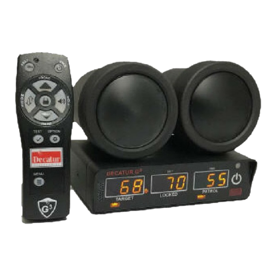
G3™ Features The G3™ is a modern traffic radar device offering many advanced capabilities . It includes 32-bit floating point digital signal processing (DSP), a versatile detachable computer/display unit, a Ka band directional antenna, and an easy-to-use Infrared (IR) remote control . -
Page 9: About This Manual
About This Manual TThis manual contains valuable information to help you set up, use and maintain your G3™, so you can extend its life and keep it at peak performance . Please take a moment to read through it and keep it handy for future reference . - Page 10 Your G3™ radar unit includes selections from the following components: Detachable Computer/ IR Hand Remote Display Unit Various Connector Cables Ka Band Directional Antenna Various Mounting Brackets Optional VIP 7/October/2020...
-
Page 11: Quick Start
1.0 Quick Start Use the following instructions to quick start your G3™: • With all cables and antennas attached, plug the cigar plug of the radar into a powered 12VDC cigarette lighter receptacle in the patrol motor vehicle . • Press the PWR button on the front display to power up the radar unit . The radar will run through a brief self-test which includes illuminating all display segments . -
Page 12: Installation
2.1 Separating the Computer/Display Unit (optional) If the space in your motor vehicle is at a premium, you will appreciate the G3™ compact size and versatile components . You can separate and remotely mount the computer unit from the display unit . - Page 13 Pull the display from the computer and note the 9-pin connectors on each half of the unit . Screw two standoffs (included with the display separation kit) into the holes next to each connector on the display unit . These standoffs are used to attach the two pieces with the 9-pin connector cable .
-
Page 14: Mounting And Connecting The Computer/Display Unit
2.2 Mounting and Connecting the Computer/Display Unit WARNINGS • Do not place the G3™ components in locations that will obscure the driver’s view of the road . • Double-check each component to ensure it is securely mounted . In an accident, a loose component could strike an occupant of the motor vehicle . • Do not place the G3™ computer, antennas, cables, or brackets in your motor vehicle’s air bag deployment zones . - Page 15 Figure 2.2a The antenna quick-disconnect connectors plug into the computer unit in the above locations . Power Cable WARNINGS • Be sure to plug the power connector into the computer unit first before plugging the power plug into the auxiliary power source . If the power source is on, it may damage the unit .
- Page 16 . Figure 2.2d Align the latch on the top of the Ethernet plug with the notch on the computer Ethernet receptacle . WARNINGS • Only use factory authorized antenna cables. Substitution of non-authorized cables can affect the operation of the G3™ 7/October/2020...
-
Page 17: Mounting And Connecting The Antenna
On the back of the computer unit there is a female DB-9 connector marked “SERIAL” that allows you to connect the G3 ™ to other devices (i .e . display signs, in-car video, PCs, or the VIP (Vehicle Interface Portal) . - Page 18 Front Antenna Mounting When mounting the front antenna bracket to the windshield use the following bullet points to help in determining the proper location . • Make sure that you Do Not mount the antenna in the deployment path of the air bag or where it will obstruct the driver's vision .
- Page 19 . • To reduce interference, position the antenna away from the patrol motor vehicle's display, fans, engine, laptops and the G3™ computer unit . • When removing other optional brackets that have suction cups, use the tabs on the suction cups to break the vacuum seal .
-
Page 20: Installation Check
After you have mounted the antenna, plug one cable end into the antenna and the other end into the antenna receptacle on the computer/display unit . If you are using only one antenna, you must connect it to the FRONT antenna receptacle . -
Page 21: Vip Installation (Optional)
2.5 VIP Installation (Optional) If your G3™ has come with the optional Vehicle Interface Portal™ (VIP™) then use the following installation instructions . WARNING • Before connecting the VIP™, ensure all devices, including the motor vehicle and radar are powered off . 2.5.1 Connecting to the Radar Connect the VIP's™... -
Page 22: Vip™ Activation
. Once the power-up routine has run correctly and the VIP™ message has been displayed, the next step is to make sure the G3™ computer is configured properly . To do this have the motor vehicle running but stopped . With the VIP™ properly installed try to put the radar into moving mode . -
Page 23: Configuring The Vip
. 2.5.4 Configuring the VIP™ To get the G3™ to recognize that the VIP™ has been connected it may be necessary to go into the radar’s menu feature and select the VIP™ . -
Page 24: Operating The G3
3.1 Power The PWR button on the display turns the G3™ on and off whereas the PWR button on the IR remote only turns the G3™ off . After you press the PWR button, the display illuminates with a segment check and internal circuitry verification . -
Page 25: Front And Rear Antenna
3.2 Front and Rear Antenna At power up, the G3™ antennas are in standby mode . (Standby mode is when the antenna is not transmitting .) If no antenna is connected to the unit, the FRONT and REAR lights cycle on and off and NO ANT displays in the locked and patrol windows . -
Page 26: Stationary Both Mode
Mode . 3.3.1 Using Directional Antennas When using the directional antenna that come standard with the G3™, you can use Stationary Approach Only or Stationary Recede Only Modes to isolate traffic in a one direction only . Figure 3.3.1a Tracking a motor vehicle RECEDING away from a stationary patrol motor vehicle with the radar in Stationary Mode using the FRONT antenna . - Page 27 . If neither antenna is activated (transmitting), then G3™ will display direction information in the patrol window as “ALL” for All targets, “APP”...
- Page 28 Figure 3.3.1c Stationary track Approach targets (No antenna is selected) Figure 3.3.1d Stationary track Recede targets (No antenna is selected) When an antenna is transmitting, the radar will switch to only displaying the up or down arrow corresponding to the target direction of travel .
- Page 29 Figure 3.3.1f While the FRONT antenna is selected, the down pointing arrow is illuminated while tracking an approaching motor vehicle . Figure 3.3.1g While the REAR antenna is selected, the up pointing arrow is illuminated while tracking an approaching motor vehicle . When the radar is toggled into the “Stationary Recede Only”...
-
Page 30: Moving Mode Opposite Direction
“REAR” antenna port . 3.4 Moving Mode Opposite Direction Use the G3™ in the Moving Mode Opposite Direction setting to display the speed of a target moving in the opposite direction from the moving patrol motor vehicle . These targets will be moving towards the patrol (using the front antenna) or away from the patrol (using the rear antenna) . -
Page 31: Moving Mode Same Direction
While the REAR antenna is selected, the down pointing arrow is illuminated while tracking a receding motor vehicle in moving opposite mode . In moving opposite mode, the G3™ simultaneously processes and displays the patrol and target motor vehicle speeds . Detected target speeds will appear in the TARGET window . -
Page 32: Fastest Mode
. The G3™ uses directional antennas so there is no need to manually select faster or slower modes in same direction . The G3™ does this automatically for you . 3.6 Fastest Mode... -
Page 33: Locking A Speed
Figure 3.6a Evaluating multiple targets in Faster Mode . 3.7 Locking a Speed Pressing the LOCK button transfers the target speed and direction information currently displayed in the TARGET window to the LOCKED window . After locking the speed, the radar unit continues to process speeds and display target speeds in the TARGET window . -
Page 34: Range Setting
3.8 Range Setting You can adjust the range (sensitivity) of the G3™ in each of the three operating modes independently: • Moving Opposite Mode • Moving Same Lane Mode • Stationary Modes The G3™ can track the speed of targets that exceed 914 meters when the unit is set at maximum range . The range setting is available in the main menu location . -
Page 35: Stopwatch Operation Mode
. The center “locked” window should display “STW” to indicate you have activated the stopwatch function . Figure 3.9 The Locked window will display "STW" whenever the G3™ is operating in the Stopwatch Mode The three numeric windows display time, distance, and speed . -
Page 36: Km/H
Once you have an established measurement area, use the FRONT ANTENNA BUTTON or the REAR ANTENNA BUTTON to increase or decrease the distance of the measurement area in meters . The LOCKED window will show the distance when adjusting but will revert to displaying STW after a few seconds of no distance change . -
Page 37: Computer/Display Unit
4.0 Computer/Display Unit Figure 4a The G3™ front display . The G3™ display contains a photocell that automatically dims the display at night for less glare and makes the display brighter in daylight conditions, so you can easily read the display . -
Page 38: Display Windows
ERROR DISPLAY: When an error occurs, one of the following appears in the display windows: LOW VOLT: Low voltage Figure 4.1a The G3™ front display showing LOW VOLT error display . RFI: Radio Frequency Interference Figure 4.1b The G3™ front display showing RFI error display . -
Page 39: Indicator Lights
4.2 Indicator Lights FAST: The FST icon light is used to indicate when the radar is in faster or fastest mode . Pressing the FASTER button again will return the unit to normal operation and the FASTER light will shut off . Figure 4.2.1a The Fast light ANT FRONT and REAR: Indicates which antenna is transmitting . - Page 40 OPP and SAM: Indicates what moving mode the radar is in . In opposite moving mode, OPP is illuminated while in same direction mode, SAM is illuminated . Figure 4.2.1d OPP and SAME indicator lights TARGET DIRECTION INDICATORS: Indicates what direction of travel the target is moving relative to the patrol motor vehicle .
-
Page 41: Antenna
5.0 Antenna The G3™ Ka-band Directional antennas are incredibly strong, yet compact and lightweight . Figure 5a Front view of the G3™ Ka directional antenna . Figure 5b Rear view of the G3™ Ka directional antenna 7/October/2020... -
Page 42: Ir Remote
6.0 IR Remote Figure 6a The S795-41-0 IR remote-control unit . 7/October/2020... - Page 43 FAST button and the other one is located on the front face . 6.1 Control Buttons POWER (PWR): powers the G3™ off . The G3™ will save all user settings on power down . OPTION: Pressing the OPTION cycles through a list of changeable settings in the primary menu .
- Page 44 Figure 6.1a The G3™ front display showing radar tracking a target at 50 km/h and showing a volume level of 5 during a volume button press . FAST (FAST): Controls the Faster/Fastest Mode feature when you are evaluating multiple targets .
- Page 45 Rear antenna button to decrement through the settings . Figure 6.1b The G3™ front display showing radar menu range or sensitivity display . (b) SQELCH Sets squelch mode . Selects the type of Doppler audio you hear . In squelch mode, the sound heard is only from the Doppler tone for the currently displayed target .
- Page 46 . There are 8 levels of brightness (1 – 8) where 8 is the brightest setting . Figure 6.1d The G3™ front display showing menu DIM (AUTO and MANUAL setting of 1) (d) BEEP Turns on or off the beep . Press the front or rear antenna button to toggle between off and on .
- Page 47 (g) VIP – AUTO or MANUAL setting AUTO for Automatic switching between Stationary and Moving mode . Man for Manual switching of modes . Figure 6.1h The G3™ front display showing menu selection of VIP MANual or AUTOmatic mode switching . 7/October/2020...
- Page 48 . Figure 6.1i The G3™ front display showing menu selection of CITY/HIGHWAY use . PATROL SPEED LOCK, RECALL and BLANKING This option locks the patrol speed at the time you lock the target speed .
-
Page 49: Ir Remote Battery Replacement
6.1 IR Remote Battery Replacement To add or replace batteries for the remote control, turn the remote over and locate the battery cover . Press the small detent as shown below and push forward . Slide the cover off to expose the battery compartment . - Page 50 Always use high quality alkaline AAA batteries to power the remote . Install batteries as shown below . Replace battery cover before placing remote back into service . • If the G3 is used in cold weather, the alkaline batteries may not deliver enough current to drive the IR emitter properly . In this case, use a high-quality Lithium AAA rated for low temperature .
-
Page 51: Communication System Controls
7.0 Communication System Controls You can configure the G3™ through the serial communications (COM) port on the rear panel to communicate with PCs, speed signs, and in-car video systems, such as the Decatur Electronics Responder 1000™ in-car video system . The communications cable does not come with your order and can be purchased separately from Decatur Electronics . -
Page 52: Angular Interference (Cosine Effect)
• The Doppler tone is corrupted with noise. • Speeds are irregular and do not provide valid tracking history. • Erroneous speeds appear to track with the engine speeds. 8.2.1 Angular Interference (Cosine Effect) When operating in the Stationary Mode, the cosine effect causes the radar to display a speed, which is lower than the actual motor vehicle speed . This condition exists when the target motor vehicle’s path is not parallel to the antenna, including conditions such as the motor vehicle traveling on a curve or a hill . -
Page 53: Fan Interference
. The radar will display an incorrect target speed, because it is using an incorrect patrol speed . With the DSP algorithms the G3™ uses, this error will not occur . 7/October/2020... -
Page 54: Electromagnetic Interference (Emi)
This type of interference occurs when the radar loses track of a target motor vehicle, because the target is reflecting two or more signals, which are interfering with each other . The G3™ is immune to multi-path cancellation . 8.2.7 Patrol Harmonics... -
Page 55: Radio Frequency Interference (Rfi)
. For this type of interference to occur, the radar unit must be operating very close to the radio transmitter . The G3™ contains an RFI detection circuit that detects excess radio frequency energy . When stray radio frequency energy reaches an excessive level, the system displays the RFI message and stops processing and displaying speeds . -
Page 56: Motor Vehicle Ignition Interference
Pressing the TEST button initiates a comprehensive system self-test, which checks the numeric displays and runs a target and patrol speed simulation . The G3™ will not power down during a self-test and checks the following: DISPLAY TEST: Verifies that the digit segments and status LED lights are working correctly and that none of the pixels in the number segments are missing . - Page 57 Figure 9.1a All LED segments show for sucessful LED testt SPEED SIMULATION TEST: The G3™ verifies the speed accuracy using a series of synthesized Doppler frequencies corresponding to simulated speeds: A patrol speed sequence of 55, 85 and 100 km/h is processed first followed by a target test sequence of 40, 70, 100 and 130 km/h .
- Page 58 Target speed test sequence of 40, 70, 100 and 130 . Figure 9.1c TARGET test sequence CIRCUITRY TEST: Checks the internal circuitry . If the unit passes all internal checks, the message TEST PASS displays in the display windows . Figure 9.1d Successful circuitry test 7/October/2020...
-
Page 59: Road Test
9.2 Road Test After the radar unit passes the self-test you may want to conduct a road test during each shift to confirm that the patrol motor vehicle’s speedometer matches the unit’s patrol speed . The road test verifies that the radar unit’s patrol speed and the motor vehicle speedometer are within ±... -
Page 60: Care, Cleaning, And Storage
• Avoid spilling food, beverages, and other liquids and substances on the radar device . • When you are not using or transporting the device, store it in its original packaging . • To clean the radar device, dust it with a soft clean cloth, which is free of cleaning solutions . • The G3™ can withstand temperature variations, however, only the antenna is weather resistant . • Insert and remove the connectors by following the correct connect and disconnect procedures . WARNING • In case your unit has a blown fuse, please replace the fuse with another fuse rated at the same capacity . -
Page 61: Specifications
11.0 Specifications 11.1 Mechanical Display Unit Dimensions 13 .3 cm x 3 .68 cm x 1 .8 cm Weight 0 .11 kg Computer Unit Dimensions 13 .33 cm x 3 .68 cm x 6 .35 cm Weight 0 .45 kg Hand-Held Remote Dimensions 11 .58 cm x 4 .00 cm x 2 .84 cm... -
Page 62: Speed Range
Current draw (A) with 13.6VDC applied in various modes: Standby (antenna OFF) 0 .17 amperes Ant . ON, no targets displayed 0 .33 amperes Ant . ON, 55 target displayed 0 .36 amperes Ant . ON, 20 target, 35 patrol 0 .40 amperes Ant . -
Page 63: Ised Information
12.0 ISED Information This device contains license-exempt transmitter(s)/receiver(s) that comply with Innovation, Science and Economic Development Canada’s license-exempt RSS(s) . Operation is subject to the following two conditions: (1) This device may not cause interference . (2) This device must accept any interference, including interference that may cause undesired operation of the device . -
Page 64: Radiation Exposure Statement
13.0 Radiation Exposure Statement This equipment complies with ISED radiation exposure limits set forth for an uncontrolled environment . This equipment should be installed and operated with minimum distance 20 cm between the radiator and your body . Déclaration d'exposition aux radiations Cet équipement est conforme aux limites d'exposition au rayonnement ISED établies pour un environnement non contrôlé... -
Page 65: Canadian Industry Certificates Of Technical Acceptability
13.1 Canadian Industry Certificates of Technical Acceptability 7/October/2020... - Page 66 7/October/2020...
-
Page 67: Frequently Asked Questions (Faq)
(sensitivity) level . If this problem continues, contact Decatur Electronics . Q. Does the G3™ interface with in-car video systems? A . Decatur’s traffic safety radar devices will interface with various in-car video systems using its SERIAL port . Please call your in-car video supplier to see if their device works with your Decatur radar device . -
Page 68: Service
15.0 Service 15.1 Warranty THREE-YEAR RADAR WARRANTY Decatur Electronics guarantees the G3™ to be free from defects in workmanship and material and to operate within specifications for a period of three years . During this period, Decatur Electronics will repair or replace, at its option, any component, found to be defective, without cost to the owner providing you return the unit to a Decatur authorized service provider . -
Page 69: Service Return Procedure
Service Providers . The customer is responsible for paying for shipping to the Service Provider . On warranty items Decatur Electronics will pay return shipping (ground freight) from the Service Provider to the customer . -
Page 70: How To Order Additional Products
16.0 How to Order Additional Products You can order upgrades (when available) to the G3™ from Decatur Electronics as well as different antenna cable lengths and mounting brackets . Contact the Decatur Sales Representative . . Antennas (for both front and rear mounts) -
Page 71: Appendix A: Communications Port
Pin 2: RS232 transmit out of G3™ radar . Pin 3: RS232 receive into the G3™ radar . Pin 4: VIP (Vehicle Interface Protocol GEN 2) input into G3™ radar . Pin 5: Signal/power ground . Pin 6: No connection . -
Page 72: Appendix B: Communications Port - Serial Protocols
[hundreds][tens][ones]<CR> (<CR> = ASCII decimal value 13) The G3™ sends the data in this sequence when the TARGET or PATROL speed display changes, or when the MODE or antenna selection changes . During the test sequence the target and patrol speeds transmit, but the display segment check data do not . -
Page 73: Appendix C: Menu Features
Appendix C: Menu Features The menu feature allows the operator to fine tune some of the settings of the radar . To activate the menu feature, press MENU button . Pressing OPTN steps through the menu items and the antenna buttons change the settings . -
Page 74: User Notes
USER NOTES 7/October/2020... - Page 76 www.DecaturElectronics.com 16990 Goldentop Road, San Diego, CA, 92127, USA 800 .428 .4315...
Need help?
Do you have a question about the G3 and is the answer not in the manual?
Questions and answers
when i power up the unit shuts off right away