Advertisement
Quick Links
Advertisement

Summary of Contents for Aventics G3 Series
- Page 1 G3 Series Wireless Auto Recovery Module Quick Start Manual...
- Page 2 G3 Series Wireless ARM Quick Start Manual Conditions for use of this product (1) AVENTICS G3 Manifold ("the PRODUCT") shall be used in conditions; i) Where any problem, fault or failure occurring in the PRODUCT, if any, shall not lead to any major or serious accident.
-
Page 3: Table Of Contents
G3 Series Wireless ARM Quick Start Manual Table of Contents PAGE Auto Recovery Module (ARM) Introduction ..................4 1. ARM Process Flowchart ........................5 2. Wireless ARM ............................ 6 2.1 Protocol/Firmware Compatibility 3. Connecting to the Wireless ARM (Computer or Mobile Device) ............7 3.1 Network SSID/Security Key... -
Page 4: Auto Recovery Module (Arm) Introduction
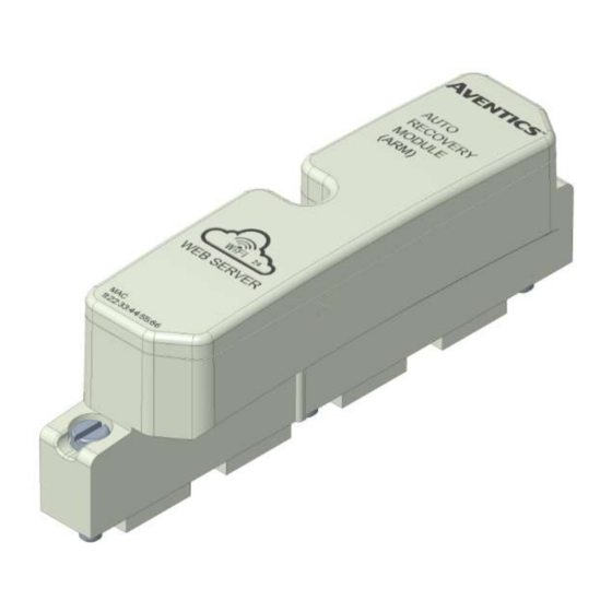
G3 Series Wireless ARM Quick Start Manual Auto Recovery Module (ARM) Introduction The Auto Recovery Module (ARM) is an optional memory module that is installed between the node and the valve adapter module and is used to backup the manifold system parameters even during catastrophic failure. During the power-up process the communication module reads the configuration of the manifold, including any user settable parameters of I/O modules, and stores the information in its non volatile memory. -
Page 5: Arm Process Flowchart
G3 Series Wireless ARM Quick Start Manual ARM Process Flowchart ARM function is described in the following flowchart CONFIG ERROR CONFIG ERROR XFER ARM TO G3 XFER G3 TO ARM CONFIRM XFER CONFIRM XFER G3 TO ARM YES ARM TO G3 YES... - Page 6 G3 Series Wireless ARM Quick Start Manual Wireless ARM The Wireless ARM supports standard ARM functionality with the addition of a WIFI accessible diagnostic web server. The web server allows the user to connect to the Wireless ARM to access manifold parameters and diagnostics using any WIFI enabled device including computers, tablets and smartphones.
-
Page 7: Connecting To The Wireless Arm (Computer Or Mobile Device)
G3 Series Wireless ARM Quick Start Manual Connecting to the Wireless ARM (Computer or Mobile Device) Once a G3 manifold equipped with a Wireless ARM is powered on; the Wireless ARM will broadcast it’s SSID. Locate the Wireless ARM broadcast ID On the computer or mobile device;... - Page 8 G3 Series Wireless ARM Quick Start Manual Open an internet browser and connect to the G3 Wireless ARM webserver by typing the IP address. (default IP address HTTP:// 192.168.4.1). “View Only” and “Configuration & Parameter changes” buttons are displayed. -View Only – connects to the G3 Webserver with read only access.
-
Page 9: Wireless Arm Webserver In "View Only" Mode
G3 Series Wireless ARM Quick Start Manual Wireless ARM Webserver in “View Only” mode “View Only” mode allows the user read only access. Configuration and parameters are locked and unable to be modified. In this mode you can monitor the condition of all of the modules in the G3 sub-bus network. -
Page 10: Password Access
G3 Series Wireless ARM Quick Start Manual Wireless ARM Webserver in “Configuration & Parameter Changes” mode Once a G3 manifold equipped with a Wireless ARM is powered on the Wireless ARM will broadcast it’s SSID. Password Protected Access Enter password to Access the Configuration & Parameter web pages. - Page 11 G3 Series Wireless ARM Quick Start Manual Dashboard The G3 Wireless ARM Dashboard is displayed. Select the “CONFIGURATION” tab for access to G3 Communication module parameters. TDG3ARMQS1-1EN 03/21 Subject to change without notice www.Emerson.com...
- Page 12 G3 Series Wireless ARM Quick Start Manual Configuration G3 Communication Module Parameters Select the menu options button to access the “DIAGNOSTICS” tab Select the “DIAGNOSTICS” tab for access to G3 manifold diagnostics TDG3ARMQS1-1EN 03/21 Subject to change without notice www.Emerson.com...
- Page 13 G3 Series Wireless ARM Quick Start Manual Diagnostics The G3 Diagnostics Webpage is displayed. Select the Valve Driver Module to display the coil diagnostic information TDG3ARMQS1-1EN 03/21 Subject to change without notice www.Emerson.com...
- Page 14 G3 Series Wireless ARM Quick Start Manual The Valve Driver Module coil diagnostic information is displayed. Here you can turn on Output Forcing to test-fire valve coils and outputs. To force fire valves and/or other outputs you will need to turn on “Output Forcing”...
- Page 15 G3 Series Wireless ARM Quick Start Manual When you turn on “Output Forcing” you will be prompted to authorize this feature via Two-Factor Authentication (2FA). To initiate Output Forcing, first click “SUBMIT REQUEST” to being 2FA. 2FA can be completed directly from the Graphic Display on the G3 Communication Module, or through the embedded G3 Webserver.
- Page 16 G3 Series Wireless ARM Quick Start Manual Option 1 – Authentication via the G3 Graphic Display: Once 2FA has been initiated through the Wireless ARM webpage, the Graphic Display on the G3 Communication Module will read “ENABLE WIFI OUTPUTS”. To complete the 2FA process and enable output forcing, click the SET button on the module.
- Page 17 G3 Series Wireless ARM Quick Start Manual Option 2 – Authentication via the G3 Comm Module Webpage: Once 2FA has been initiated through the Wireless ARM webpage, you can authorize the second phase of the authentication process via the G3 Node’s embedded webpage. To do so, first connect to the Comm Module via an Ethernet cable, and by entering the module’s IP Address into a web browser.
- Page 18 G3 Series Wireless ARM Quick Start Manual On the Wireless ARM webpage the blue button text will now read “ACCEPT”. Click this button to continue with Output Forcing turned on. Output Forcing will remain on until it is turned off via the Wireless ARM webpage or the G3 Graphic Display, or until the WIFI connection with the ARM is terminated.
-
Page 19: Returning Wireless Arm To Factory Defaults
ARM. Click the “Reset to factory defaults” button. Technical Support For technical support, contact your local AVENTICS distributor. If further information is required, please call AVENTICS Technical Support Department at (248) 596-3337.
Need help?
Do you have a question about the G3 Series and is the answer not in the manual?
Questions and answers