Table of Contents
Advertisement
Quick Links
Advertisement
Table of Contents

Related Manuals for DESSALATOR PRO COMPACT D90


Summary of Contents for DESSALATOR PRO COMPACT D90
- Page 1 PRO COMPACT & CAD – D90 to D200 90 to 200 liters/hour – 230 (or 400V) PRO COMPACT PRO CAD ASSEMBLY AND USER MANUAL Dessalator® ZI des 3 Moulins 282 rue des Cistes 06600 Antibes, France www.dessalator.com contact@dessalator.com PRO COMPACT & CAD D90 to D200 v2.4 (03/21)
-
Page 2: Table Of Contents
High-pressure pump ....................26 Spare Parts ..........................26 Appendix A1: How do watermakers work? ................27 Appendix A2: Mounting of the DESSALATOR® high-pressure nozzles ....... 28 Appendix A3: Manual Rinsing Procedure ................29 Appendix A4: Instructions for the Sterilizing Cartridge ............30 Appendix A5: Troubleshooting .................... -
Page 3: Copyright / Disclaimer
Copyright / Disclaimer Dessalator® ZI des 3 Moulins, 282 rue des Cistes Bâtiment Euro 92 06600 Antibes, France www.dessalator.com contact@dessalator.com +33 4 93 95 04 55 PRO COMPACT & CAD D90 to D200 v2.4 Page 3... -
Page 4: List Of Components
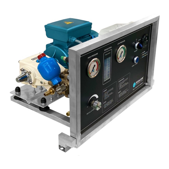
List of Components Hull Valve Ø Must be placed as low as possible in the boat so as to avoid drawing in any Ø Must be installed towards the back for a motorboat, or centered near the keel for a sailboat. The ribs of the strainer should be placed towards the front the boat to force the entry of water by scooping during navigation. - Page 5 Front Control Panel The control panel is separate from the engine (for the CAD version) and incorporated into the frame (for the COMPACT version). It allows you to control the watermaker and is made up of the following elements: Ø A high-pressure manometer Ø...
- Page 6 Motor Block Ø The HP motor block can push seawater out to 60-65 Bars. Ø Composed of the 230 or 400 Volts motor. Ø Must be installed in a ventilated space. Ø The motor block is separate from the control panel for the CAD version or is incorporated in a frame which contains the control panel for the COMPACT version.
-
Page 7: Assembly
Ø 4 special DESSALATOR® fittings* for high-pressure piping (see assembly procedure in Appendix A2). § * Including one 90° elbow fitting for the back of the control panel, which can swivel 360°. -
Page 8: Seawater Inlet
2) Seawater inlet Seawater inlet valve Ø The strainer should be placed as low as possible beneath the waterline so that it does not draw in any air. It should be placed far from the discards. Ø Pierce the hull with a Ø 27mm hole saw. Ø... - Page 9 Cartridge prefilter block Ø The prefilter must also be installed beneath the waterline to ensure a better yield/output. It must be easy to access. Ø The fixing bracket is reversible to allow you to adjust the installation height. Ø For the inlet and outlet , piping connections must be made with Tricoflex Ø...
-
Page 10: Motor/Pump Block
3) Motor Block Ø To ensure optimal production, the assembly of the high-pressure motor block must be completed in a horizontal position and in an area protected from water sprays. Ø Use the 2 stainless steel legs under the 2 motors to fix the motor block. Leave a few centimetres of wiggle room around it. -
Page 11: Electric Connections
4) Electric connections WARNING! Never work with the power on! Turn off the power of your entire system. Electrical connection of the 230 Volts (or 400 Volts) motor: Electrical connections of the 230 Volt pre-pump: 5) Membrane Block Ø The membrane block should preferably be mounted horizontally (on the base or side). -
Page 12: Control Panel
6) Control panel The control panel must be mounted on a vertical panel. Ensure unrestricted access to the back of the control panel, this will make connections easier. You should place it in a place where the light indicators are visible. Example: below or on the sides of cupboards, under the chart or centre table, on the front panel of a rear berth etc. - Page 13 COMPACT version: Black high-pressure hose to connect the membrane outlet to the pressure sensor of the control panel. Blue Serto hose to connect the water production outlet of the membranes to the inlet of the switchboard probe. Tricoclair hose with an inside Ø of 10 mm (allow a length of 20 meters), which you must connect either directly to the tanks, or to the distribution clarinet or to the inlet of the fresh water unit, provided that there is no valve at the outlet of the fresh water tank.
-
Page 14: Mini Remote Control (Optional)
7) Mini Remote Control (optional) General presentation: The Dessalator® Mini Remote Control Dessalator allows you to manage and monitor the watermaker. You can start and shut down the machine simply by pressing a single button on the Mini Remote Control. The 3 light indicators on the Mini Remote control have the same functions as the 3 lights on the watermaker itself. -
Page 15: Start-Up
Start-Up 1) Precautions before start-up WARNING! Before starting-up, check that the valves are open. Mandatory Ø When using the device for the first time, after changing the filter, after the boat has been grounded or stopped for a long time, you should flush the system using fresh water by operating the three-way valve on the pre-pump. -
Page 16: Starting-Up The Watermaker
2) Starting-up the watermaker CAD version: Follow the procedure below: Ø Set switch to "Manual" and press START or press on the Mini Remote Control (which is optional, see procedure in paragraph 5). Ø The system is rinsed for 5 seconds using fresh water. Ø... - Page 17 COMPACT version: Follow the procedure below: Ø Set switch to "Manual" and press START or press on the Mini Remote Control (which is optional, see procedure in paragraph 5). Ø The low pressure pump starts up, the needle on the low pressure gauge rises to the green area.
-
Page 18: Stopping The Watermaker: Without Rinsing Of The Membranes
3) Stopping the watermaker: without rinsing of the membranes It is not necessary to rinse your membranes if you use your watermaker regularly. CAD version: Follow the procedure below: Ø Set switch to "OFF" or press on the Mini Remote Control press (which is optional, see procedure in paragraph Ø... - Page 19 Version COMPACT : Follow the procedure below: Ø Set switch to "OFF" or press on the Mini Remote Control press (which is optional, see procedure in paragraph Ø Lower the pressure by turning the pressure regulating dial to the left (counterclockwise) until the needle of the high-pressure gauge reaches its minimum.
-
Page 20: Stopping The Watermaker: With Automatic Rinsing Of The Membranes
4) Stopping the watermaker: with automatic rinsing of the membranes A rinsing must be carried out if the watermaker is not going to be used for more than 3 weeks. CAD version : Follow the procedure below: After using the watermaker, do not turn it off. Ø... - Page 21 COMPACT version : Follow the procedure below: After using the watermaker, do not turn it off. Ø While the watermaker is still running, turn the pressure regulating dial all the way to the left (counterclockwise) to lower the pressure of the gauge Ø...
-
Page 22: Using The Mini Remote Control (Optional)
5) Using the Mini Remote Control (optional) Once you start-up the system for the first time using the control panel, you can use the Mini Remote Control to perform the following: monitor the state of the system, stop, or schedule a delayed shutdown. -
Page 23: Operation
Operation Membranes are delicate components Reverse osmosis membranes must be carefully maintained as they are the most sensitive parts of your system. Follow the instructions given to avoid damaging them and voiding the warranty. The nominal production capacity of the watermaker is given for a temperature of 25°C for seawater and depend on the salinity of the seawater in your navigation area. -
Page 24: Maintenance
Maintenance WARNING! In case of risk of frost, we recommend emptying the flowmeter located on the control panel, disconnect the output pipe (blue) and blow or inject air into this pipe while alternating pressing on the small button of the solenoid valve located at the back of the control panel. -
Page 25: Sterilizing The Membranes
3) Sterilizing the membranes When should the membranes be sterilized? Under normal circumstances, a monthly and regular rinsing of the membranes is enough for their maintenance. If you do no use the watermaker for a while and cannot perform a monthly rinsing, membrane sterilization is necessary. -
Page 26: High-Pressure Pump
Spare Parts DESSALATOR® devices, which have a high reliability and long lifetime, generally do not require costly servicing. An accident is always possible (operation with low water level, accidental overpressure, impact, etc.). -
Page 27: Appendix A1: How Do Watermakers Work
Appendix A1: How do watermakers work? How does reverse osmosis work? Pressurized seawater enters the membranes which, similarly to "molecular sieves", only let the fresh water molecules pass. Most of the dissolved solid particles do not cross the membranes. These residues are evacuated with the discharge water. -
Page 28: Appendix A2: Mounting Of The Dessalator® High-Pressure Nozzles
Appendix A2: Mounting of the DESSALATOR® high-pressure nozzles 1. Screw the brass fitting onto the high-pressure hose counter-clockwisela all the way to the vertical mark on the outside of the fitting. 2. Place the brass plug in the stainless steel nut and tighten it firmly: 3. -
Page 29: Appendix A3: Manual Rinsing Procedure
The valve is in the fresh water position for manually rinsing the circuit with fresh water or for sterilization (see below). Your DESSALATOR® system is equipped with an automated rinsing feature, below is the procedure to follow if you would like to manual rinse it. -
Page 30: Appendix A4: Instructions For The Sterilizing Cartridge
Appendix A4: Instructions for the Sterilizing Cartridge With the watermaker OFF: Ø Close the seawater inlet valve. Ø Open the sterilizing cartridge: be careful not to lose the O-ring. Ø Remove the top screen. Ø Place the foam at the bottom of the filter. Ø... -
Page 31: Appendix A5: Troubleshooting
Appendix A5: Troubleshooting PROBLEM POSSIBLE CAUSES SOLUTIONS Leak on the pressure regulator on - Tighten the cable gland with a 17 Control cable gland is loosened the front ot the control panel mm open-end wrench - Check the diameter of the pipes, -Reduced water inlet or air inlet the tightening of the clamps and the cleanliness of the filter. -
Page 32: Appendix A6: Guide Of The Indicator Lights Of The Mini Remote Control
Appendix A6: Guide of the Indicator Lights of the Mini Remote Control PRO COMPACT & CAD D90 to D200 v2.4 Page 32... -
Page 33: Appendix A7: Circuit Diagram Of The Electronic Board
Appendix A7: Circuit diagram of the electronic board PRO COMPACT & CAD D90 to D200 v2.4 Page 33... -
Page 34: Appendix A8: Schematic Drawing Compact Version
Appendix A8: Schematic drawing COMPACT version: PRO COMPACT & CAD D90 to D200 v2.4 Page 34... -
Page 35: Appendix A8: Schematic Drawing Cad Version
CAD version: PRO COMPACT & CAD D90 to D200 v2.4 Page 35... - Page 36 Dessalator® ZI des 3 Moulins, 282 rue des Cistes Bâtiment Euro 92 06600 Antibes, France www.dessalator.com contact@dessalator.com +33 4 93 95 04 55 PRO COMPACT & CAD D90 to D200 v2.4 Page 36...
Need help?
Do you have a question about the PRO COMPACT D90 and is the answer not in the manual?
Questions and answers