Table of Contents
Advertisement
Available languages
Available languages
Quick Links
Advertisement
Chapters
Table of Contents

Related Manuals for C-LOGIC 3400


Summary of Contents for C-LOGIC 3400
- Page 1 C-LOGIC 3400 MANUAL DE INSTRUCCIONES Localizador de cables multifunción...
-
Page 2: Table Of Contents
Utilizando el comprobador ......3 3. Mantenimiento y Rep aración ... 15 1. lntroducción........4 3.1 Cambio de pilas........15 1.1 Características C-LOGIC 3400....4 1.2 Botones y componentes......5 2.Uso del comprobador......8 2.1 Comprobación de cable de red....8 2.1.1 Indicador de error........9... -
Page 3: Garantía Limitada Y Limitación De La Responsabilidad
LAS INSTRUCCIONES DE SEGURIDAD responsabilidad DESCRITAS EN EL MANUAL DE USUARIO. LEA Este producto C-LOGIC 3400 de C-LOGIC estará libre de LOS MANUALES DE USUARIO ANTES DE defectos de material y mano de obra durante un año a partir UTILIZAR EL PROBADOR. -
Page 4: Lntroducción
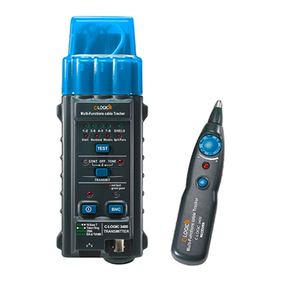
& ADVERTENCIA 1. lntroducción PARA EVITAR DESCARGAS ELÉCTRICAS Y C-LOGIC 3400 es un comprobador de cables de red de LESIONES, CUBRA EL COMPROBADOR CON mano, ideal para la instalación, medición, mantenimiento UNA CUBIERTA PROTECTORA CUANDO NO o inspección de cables coaxiales (BNC), UTP y STP. - Page 5 1.2 Componentes y Botones Multi-Function Wire Tracer SHIELD Short Reversed Miswire Split Pairs TEST CONT TONE red fauit green good 10 Base T Token Ring A. Transmisor (principal) 258A TRANSMITTER EIA&TIA568 B. Receptor C. Caja de emparejamiento (remoto)
-
Page 6: Indicador De Error
2.Uso del comprobador 1.Interruptor de encendido 2.1 Prueba de cable de red 2.Indicador de encendido 3.Botón de test de cable coaxial "BNC" ADVERTENCIA 4.Indicador de cable coaxial PARA EVITAR DESCARGAS ELÉCTRICAS Y 5.Interruptor de función LESIONES, DESACTIVE EL CIRCUITO MIENTRAS SE 6.Indicador "CONT"... -
Page 7: Modo Depuración
Circuito abierto: El circuito abierto no se ve comúnmente y Ejemplo: el par de cables 1-2 y el par 3-6 están en cortocircuito. En el modo de prueba, los indicadores de error por lo tanto no se incluye ninguna indicación en el comprobador. - Page 8 Ejemplo: El par de cables 1-2 y el par 3-6 están en cortocircuito. En el modo de depuración los indicadores 2.3 Test de continuidad se mostrarán como sigue: & • El par de cables 1-2 parpadea con luz verde, el indicador ADVERTENCIA del par de cables 3-6 y el indicador de cortocircuito PARA EVITAR UNA DESCARGA ELÉCTRICA Y...
-
Page 9: Seguimiento De Cable De Red
2.4 Seguidor de cable de red 2.5 Prueba de los modos de línea telefónica 2.5.1 Diferenciar el cable TIP o RING: ADVERTENCIA Ponga el interruptor del transmisor en "OFF", conecte el PARA EVITAR DESCARGAS ELÉCTRICAS Y LESIONES, NO CONECTE EL RECEPTOR A NINGUNA SEÑAL DE adaptador de cable correspondiente a las líneas telefónicas CORRIENTE ALTERNA SUPERIOR A 24V. -
Page 10: Mantenimiento Y Reparación
3. Mantenimiento y reparación 3.1 Reemplazo de pilas Cambie las pilas nuevas cuando el indicador de pilas esté encendido, retire la tapa de las pilas en la parte posterior y cambie una pila nueva de 9V. MGL EUMAN, S.L. Parque Empresarial de Argame, C/Picu Castiellu, Parcelas i-1 a i-4 E-33163 Argame, Morcín Asturias, España, (Spain) - Page 11 C-LOGIC 3400 INSTRUCTION MANUAL Multi-function wire tracer...
-
Page 12: Coi\Itei\It!I
3. Maintenance and Repair ....15 1. lntroduction ........4 3.1 Battery Replacement......15 1.1 C-Logic 3400 Fea tu res ......4 1.2 Components And Buttons ...... 5 2. Using The Tester ........ 8 2.1 Network Cable Testing ......8 2.1.1 Error lndicator. -
Page 13: Limited Warranty And Limitation Of Liability
INSTRUCTIONS DESCRIBED IN THE USER Of Liability MANUAL. READ THE USER MANUALS BEFORE This C-LOGIC 3400 product from C-LOGIC will be free from USING THE TESTER. defects in material and workmanship for one year from the date of purchase. This warranty does not cover fuses,... -
Page 14: Using The Tester
Tester or shipping purpose (ex. Calibration) the equipment under test. 1. lntroduction Using the Tester C-LOGIC 3400 is a hand held network cable !ester, & WARNING ideal for Coaxial Cable (BNC), UTP and STP Cable installation, measurement, maintenance or TO AVOID ELECTRICAL SHOCK AND INJURY, inspection. -
Page 15: Components And Buttons
1.2 Components and Buttons Multi-Function Wire Tracer SHIELD Short Reversed Miswire Split Pairs TEST CONT TONE red fauit green good 10 Base T Token Ring 258A TRANSMITTER A. Transmitter (main) EIA&TIA568 B. Receiver C. matching box (remote) -
Page 16: Using The Tester
2.Using the Tester 2.1 Network Cable Testing WARNING TO AVOID ELECTRICAL SHOCK AND INJURY, UNPOWER THE CIRCUIT WHILE PERFORMING TESTS. 2.1.1 Error Indicator A wire pair indicator flashes (indicator #13,14,15,16) indicates an error in the connection. Error indicator flashes specify an error. If more than one wire pair indicator flashes, troubleshoot on each case until all the indicators go back to GREEN(Normal). -
Page 17: Test Mode
Open Circuit: Open Circuit is not commonly seen Example: wires pair 1-2 and pair 3-6 are short circuit. and therefore no indication is included in the Tester. In test mode, the error indicators will show as following: Typically there are 2 to 4 coaxial cables pairs in the •... -
Page 18: Coaxial Cable Testing
Example: Wire pair 1-2 and pair 3-6 are short circuit. 2.3 Continuity Testing In debug mode indicators will show as follow: & • Wire pair 1-2 flashes green light, wire pair 3-6 WARNING indicator and short circuit indicator flashes red light. TO AVOID ELECTRICAL SHOCK AND INJURY, •... -
Page 19: Network Cable Tracking
2.4 Network Cable Tracking 2.5 Telephone Line Modes Testing 2.5.1 Differentiate TIP or RING wire: WARNING Turn the switch on the transmitter to “OFF”, connect TO AVOID ELECTRICAL SHOCK AND INJURY, DO the corresponding wire adaptor to the open telephone NOT CONNECT RECEIVER TO ANY AC SIGNAL lines in the network. -
Page 20: Maintenance And Repair
3. Maintenance and Repair 3.1 Battery Replacement Replace new batteries when the battery indicator is on, remove the battery cover in the back and replace a ne 9V battery. MGL EUMAN, S.L. Parque Empresarial de Argame, C/Picu Castiellu, Parcelas i-1 a i-4 E-33163 Argame, Morcín Asturias, España, (Spain) 00-05-3019...
Need help?
Do you have a question about the 3400 and is the answer not in the manual?
Questions and answers