Advertisement
OPTIMUS 400/800
Be sure to read this assembly manual thoroughly.
The relevant safety standards must first be taken into account.
Gates that have been placed before 01-11-2000 or 01-06-2001 must meet the requirements for
health and safety that have appeared in BGR 232.
Gates which were subsequently brought into service must comply with the following European
Standards:
Since 01-11-2000 DIN EN 12604 / 12605
-
Since 01-06-2001 DIN EN 12453 / 12445
-
The date of commissioning of the installation applicable here!
Drive for swing gates
Manual 16.06.001.002
Advertisement
Table of Contents

Summary of Contents for GMF OPTIMUS 400
- Page 1 OPTIMUS 400/800 Drive for swing gates Manual 16.06.001.002 Be sure to read this assembly manual thoroughly. The relevant safety standards must first be taken into account. Gates that have been placed before 01-11-2000 or 01-06-2001 must meet the requirements for health and safety that have appeared in BGR 232.
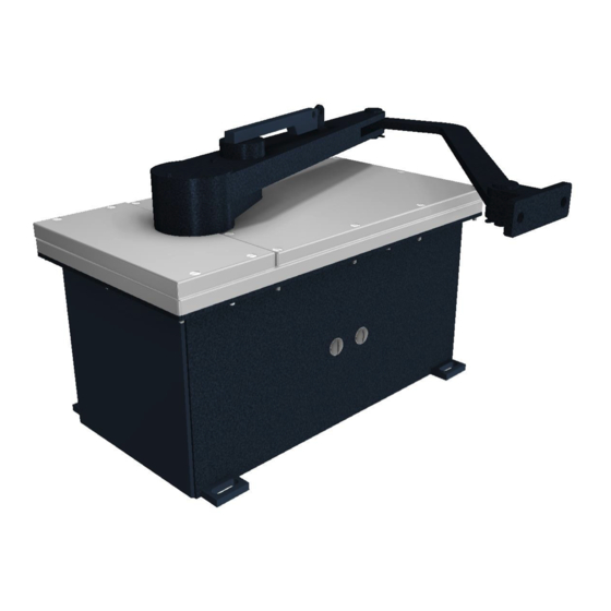
- Page 3 1. Description The drive mechanism of the type OPTIMUS consists of a water-resistant steel housing and watertight aluminium cover plates. It features a self-locking worm gear, an adjustable slip clutch (depending on the desired torque), build-in limit switches and an AC motor 230V/400V. The standard equipment includes a rotating arm with a door link bracket.
- Page 4 2. Assembly OPTIMUS 230V MONO - E - 30-07-18...
- Page 5 OPTIMUS 230V MONO - E - 30-07-18...
- Page 6 3. Setting the limit switches The limit positions should be set after assembly by shifting and tightening the switching cams (2). Limit switches (1) Switching cams (2) 4. Setting the friction clutch The friction clutch is set as follows: - Untighten the lock nut (3) and tighten the adjusting screw (4) until the swing gate can be held still manually.
- Page 7 5. Opening the swing gate in case of power failure Loosen the lever for manual control (B) counter clockwise from the pivot arm (A) and remove it. After that the gate can be opened by hand. To electrically operate the gate again, repeat the previous steps in the reverse order. First, move the gate to the position in which it was unlocked, then turn the lever for manual control (B) clockwise until the lever is back in line with the pivot arm (A) (the manual clutch can be secured by means of a padlock).
Need help?
Do you have a question about the OPTIMUS 400 and is the answer not in the manual?
Questions and answers