
Subscribe to Our Youtube Channel
Summary of Contents for TERASAKI TemBreak PRO TemView PRO
- Page 1 TemView PRO External Display for P Model SMART Moulded Case Circuit Breakers USER MANUAL Version 1.0.0 1300 NHP NHP nhp.com.au NHP Electrical Engineering Products 0800 NHP NHP nhp-nz.com...
-
Page 2: Using This Manual
Appropriate use of NHP / Terasaki products NHP / Terasaki products are intended to be used only for the applications described in the catalogue and technical documentation, which is dedicated to them. If products and components from other manufacturers are used, they must be recommended or approved by NHP or Terasaki. -
Page 3: Summary Of Changes
Summary of Changes This section highlights the details of changes made since the previous issue of this document. The versioning convention used to track changes in this document follows the structure Vx.y.z where: x: Major revision, where extensive changes are made which is generally incompatible with the previous version. Such changes may include new products and/or features, or removal of information which is no longer relevant or applicable to the previous version y: Minor revision, where changes made do not change the overall scope of the previous version, but may include additional information which complements or corrects the previous version, or provides additional clarity on an existing topic. -
Page 4: Table Of Contents
Table of Contents Using this manual Write Protection Safety Precautions Remote Write Authorization Summary of Changes Password Management Table of Contents Configuration Introduction Starting the TPED for the First Time Who Should Use This Manual? Passwords Additional Resources Password Entry Terminology and Abbreviations Password Change Product Information... -
Page 5: Introduction
Introduction The TemView PRO (TPED) enables remote and expanded configuration of the NHP/Terasaki TemBreak PRO Smart Energy (P_SE) MCCBs. The TPED allows access to extended information including instantaneous and historic energy and power measurements, status indicators, and detailed trip and alarm history, as well as reading and writing of configuration and protection settings external to the MCCB via an easy-to-use interface outside the panel or switchboard. -
Page 6: Terminology And Abbreviations
Introduction Terminology and Abbreviations Abbreviation Description Abbreviation Description Auxiliary Communications port: Plug for Smart auxiliary / MCCB Moulded Case Circuit Breaker alarm contact block Alarm: An auxiliary contact indicating trip status microSD Micro Secure Digital Maintenance Interface Port: Plug for temporary ASCII American Standard Code for Information Interchange connection to OCR testing, servicing, and maintenance... -
Page 7: Product Information
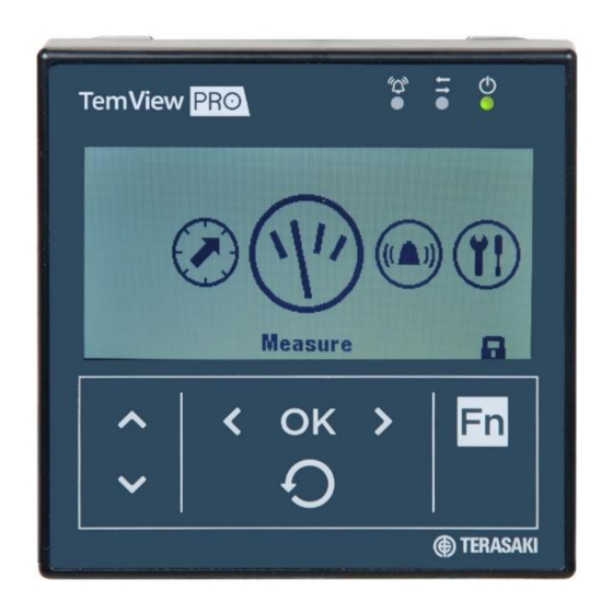
Product Information The TemView PRO (TPED) is an optional backlit LED external display which permits reading and writing data of the P_SE MCCB OCR, including protection settings, energy measurements, alarms, and event logs. It is used where direct access to the embedded display of the P_SE MCCB is not permitted, or otherwise enclosed and inaccessible. -
Page 8: Product Data
Product Information Product Data Technical Data Dimensions 97 x 97 x 46 mm (27mm behind the door) Door cut-out 92 x 92 mm Screen size 37 x 78 mm Viewing backlight Backlit blue Temperature operation -10 ° C ... + 55 ° C Pollution Category Degree of protection IP65 (rear is IP20) -
Page 9: Plugs & Ports
Plugs & Ports P_SE The TemBreak PRO Smart Energy (P_SE) MCCB is equipped with specific connectors for connecting communication devices and accessories. The Communication Input Port (CIP) are used to connect the TPCM to the MCCB, see below for their locations. Port Description Maintenance Interface Port –... -
Page 10: Installation
Installation Mechanical Installation Action Note Make a cutout in the required panel for the mounting of the TPED Insert the TPED into the cutout Use the supplied clips to hold the display in place. Connect CIP adapter cable to TPED and Refer to ANNEX - Connection Diagram section. -
Page 11: Power Supply
Installation Power Supply An external 24 Vdc supply is required for the TPED, which is delivered via the CIP adapter cable to the P_SE MCCB. The MCCB in turn requires the external power supply connection, which is connected to the MCCB in one of two ways: Direct connection to MCCB with via CIP adapter cable TPPHQTT140H (P160 / P250), or TPPHQTT160H (P400 / P630) Connection via the TPCM provided power supply. -
Page 12: Cip Adapter Cable
Installation Power Supply CIP adapter cable Below are the steps for direct connection of power supply to the TPED via the OCR via CIP adapter cable: TPPHQTT140H (P160 / P250), or TPPHQTT160H (P400 / P630). WARNING: Local wiring rules shall be respected (e.g., AS/NZS 3000: Wiring Rules) and shall provide: - Separation of the power cables and ELV / communication cables - Secure the cable along the routing. - Page 13 Installation Power Supply CIP adapter cable Action Note / Illustration Insert the CIP connector for the CIP adapter in one of the connectors marked CIP inside the circuit breaker on the left-hand side. Route the cable for the CIP adapter along the left-hand side cable channel of the circuit breaker provided for this purpose.
-
Page 14: Navigation
Navigation TPED Overview Component Description Screen Backlit monochrome LCD Signalling LED Alarm – Communication - Ready RJ9 port At the rear of the display Function “Fn” key Function dependent on the menu displayed Left and Right keys to navigate to the left and right in the menus. Left / OK / Right keys OK key: Confirm an action. -
Page 15: Main Menu
Navigation Overview Main Menu There are 5 main menus and a pop-up menu. Menu Description Protection: View and modify the LSI(G) protection settings. Measurement: View the extended detailed real-time and historic measurements values Alarm: View and modify alarms for various types of events based on system status and live monitoring of parameters, including custom alarms, PTA and Optional Alarm (OAC) contacts. -
Page 16: Protection Settings
Navigation Overview Protection Settings LSI(G) protection settings which are viewed and modified via the TPED are as follows: Notice: Refer to the P_SE User Manual for further information on protection settings and particular detail on settings dependent on specific MCCB models and ratings. Menu Description Settings... -
Page 17: Measure
Navigation Overview Measure Detailed real-time and historic measurements which are viewed and assessable via the TPED are as follows. Notice: Refer to the P_SE User Manual for further information on measurements including calculation and acquisition methods. Menu Description Measurements Designator / Description Phase and neutral Arithmetic mean = [I... - Page 18 Navigation Overview Measure Menu Description Measurements Designator / Description Active P1, P2, P3, Ptot Reactive Q1, Q2, Q3, Qtot Apparent S1, S2, S3, Stot Power Max. of each P1, P2, P3, Ptot Maximum since last reset Max. of each Q1, Q2, Q3, Qtot Max.
-
Page 19: Alarms
Navigation Overview Measure Alarms View and modify alarms for various types of events based on system status and live monitoring of parameters, including custom alarms, PTA and Optional Alarm (OAC) contacts. Menu Description Measurements Designator / Description 1-12 Custom Custom Custom Alarms See Custom Alarms Section Alarms... -
Page 20: Configuration
Navigation Overview Configuration View and modify MCCB measurement and display settings, and reset of historical measurement data, alarms and events. Menu Description Measurements Designator / Description Brightness 20 / 40 / 60 / 80 / 100% Contrast 0 / 25 / 50 / 75 / 100% Display Settings Display Mode ON / OFF... - Page 21 Navigation Overview Configuration Menu Description Measurements Designator / Description Reset All Min / Max Reset Current Min / Max Reset Voltage Min / Max Reset Power Min / Max Reset Reset PF Min / Max Yes / No Reset Frequency Min / Max Reset THD Min / Max Reset On Demand Min / Max Reset Energies Min / Max...
-
Page 22: Information
Navigation Overview Information View the status and identification information of the MCCB and historic trip and alarm logs include SMART Auxiliary counters. Menu Description Description Information Range Name TemBreak PRO P(n) Number of Poles 3 / 4 MCCB Information Description 1 MCCB Description 2 Production Date... -
Page 23: Alarms
Alarms Alarm Types The TPED allows alarming from the P_SE OCR for various types of events based on system status and live monitoring of parameters. There are three types of alarms available on the TPED based on functionality and configurability. System alarm: Correspond to predefined events internal to the OCR. -
Page 24: Priority Level
Alarms Priority Level Each trip and custom alarm is associated with it a priority level, which determines how each alarm is displayed and logged. Notice: Custom alarms are only visible using the TPED or TPCM, however, the P_SE OCR will still monitor and log any prior configured alarms without either TPED or TPCM connected. -
Page 25: System Alarms
Alarms System Alarms System alarms are produced as a result of at least one of the following pre-defined events, which are not user configurable: Internal OCR error OCR temperature alarm Disconnection of neutral Notice: PTA and System alarms are only visible on the TPED when assigned to the OAC, however, only one at a time is possible. -
Page 26: Pta (Pre-Trip Alarm)
Alarms PTA (Pre-Trip Alarm) The Pre-Trip Alarm permits monitoring and early warning of overload conditions prior to an actual LTD trip. The PTA setting is defined by two parameters which define the Pre-trip warning and Pre-trip Alarm zones and thus the behaviour of the PTA contact and status LED on the P_SE MCCB: PTA current threshold I : Threshold expressed as a percentage of I and is adjustable from 60…95%... -
Page 27: Custom Alarms
Alarms Custom Alarms Custom alarms make it possible to produce alarms based specific events and measurements made by the P_SE OCR. They are only available to be configured and displayed using the TPED and/or TPCM in conjunction with the P_SE MCCB. Up to 12 custom alarms may be individually configured for a single P_SE OCR, with each used to monitor a single event of measurement. -
Page 28: Positive Activation
Alarms Custom Alarms Positive activation In the case of a positive activation, the alarm is activated when the monitored value increases towards the pick-up threshold. This occurs when the pick-up threshold is set to a higher value than the drop-out threshold. Symbol Description Pick-up threshold... -
Page 29: Equivalent Value Activation
Alarms Custom Alarms Equivalent value activation For the equal value activation, the alarm is activated when the value measured is equal to the configured value. The activation threshold is the same as the activation value. Symbol Description Pick-up value Pick-up time delay Drop-out time delay TemBreak TemView_PRO-UM-001-EN V1.0.0... -
Page 30: Time Delays
Alarms Custom Alarms Time delays Custom alarms are activated once the pick-up threshold has been reached and the configured pick-up time delay has elapsed. Likewise, custom alarms are deactivated after the drop-out threshold is reached and the drop-out time delay has elapsed. Both pick-up and drop-out time delays are independently configurable, from a minimum 1 second to maximum 3000 seconds. -
Page 31: Custom Alarms List
Alarms Custom Alarms Custom alarms list Pick-up or Drop-out threshold value Pick-up or Drop-out time delay value Name 3Ph+N Unit Min. value Max. value Unit Min. value Max. value ✓ ✓ No assignment ─ ─ ─ ─ ─ ─ ─ ─... - Page 32 Alarms Custom Alarms Custom alarms List Pick-up or Drop-out threshold value Pick-up or Drop-out time delay value Name 3Ph+N Unit Min. value Max. value Unit Min. value Max. value ✓ Over Direct Active power [P 1000 3000 ─ ✓ Over Direct Active power [P 1000 3000 ─...
- Page 33 Alarms Custom Alarms Custom alarms List Pick-up or Drop-out threshold value Pick-up or Drop-out time delay value Name 3Ph+N Unit Min. value Max. value Unit Min. value Max. value ✓ Lagging displacement PF [Cosϕ ─ 0.01 0.99 3000 ─ ✓ Lagging displacement PF [Cosϕ...
-
Page 34: Oac (Optional Alarm Contact)
Alarms OAC (Optional Alarm Contact) The OAC is an optional alarm which can be assigned with one of several types of alarms. When the assigned alarm is activated, the alarm will display on the TPED as a pop-up notification. The OAC also has a physical contact on the P_SE which closes with the activation of the OAC alarm. Notice: The use of the OAC physical contact requires the connection of the OAC/PTA cable to the OAC port located under the front cover of the P_SE MCCB. -
Page 35: Write Protection
Write Protection WARNING: Changes and adjustments to protection settings and levels (either local or remotely) should only be performed by qualified personnel. Failure to comply may result in malfunction or damage of protective equipment, serious injury or death. Modifications made remotely via the TPED to the MCCB configuration settings may be dangerous for personnel near the circuit breaker or may cause damage to the equipment if the protection parameters are modified. -
Page 36: Password Management
Write Protection Password Management Changes to certain configuration settings are protected by varying security access levels. To enable changing of protection settings on the TPED, a password must be entered. The display indicates that its password lock status via a padlock symbol on the lower right of the display. Locked Unlocked To unlock the TPED, press the Function Key “Fn”... -
Page 37: Configuration
Configuration Starting the TPED for the First Time The first time the TemView PRO is powered up the display will ask you to choose the navigation language. Default is: English. Action Screen Select another language Confirm the selection: The screen is displayed in the language chosen. -
Page 38: Passwords
Configuration Passwords Password Entry WARNING: The default passwords should be changed during commissioning to prevent unauthorized modification to protected settings. Action Screen Open the Main menu The presence of a padlock means that the screen is locked. Open pop-up for password entry The password must be 4 figures long. -
Page 39: Password Change
Configuration Password Change WARNING: If the password is lost, it cannot be reset to factory default settings. The TPED must be replaced. Action Screen Open the Configuration menu Select the sub-menu "Change the password" Confirm the selection and enter the new password Increase/decrease the value Select the next numbers and position the... -
Page 40: Protection Settings
Configuration Protection Settings WARNING: Risk of nuisance tripping. Only qualified personnel are to set the protection levels. Failure to respect these instructions may cause death, serious injuries or equipment damage. Action Screen Ensure the Display is unlocked. Refer to Password Entry section Select protection Scroll to the required protection sub-menu... -
Page 41: Measurements Display
Configuration Measurements Display Action Screen To view the displayed measurements Select Measure from the Main Menu Scroll up or down to view the sub-menus Scroll left or right to view the sub- measurements Press the back button to return to the Main Menu Selecting a Favourite Action... -
Page 42: Setting A Custom Alarm
Configuration Setting a Custom Alarm Action Screen Ensure the Display is unlocked. Refer to Password Entry section Select Alarms Select Custom Select a free alarm slot Using the left or right arrow, set the required measurement Using the up or down arrow, scroll through the required options Once all the require parameters have been entered... -
Page 43: Troubleshooting
Verify integrity of wiring and connections. display stuck on Check for and correct any: “TERASAKI” logo Loose connection of CIP connector and cable Loose connection of CIP cable to external supply terminals Incorrect supply terminals / conductors / connector pins... -
Page 44: Annex
ANNEX Dimensions 27 mm 97 mm 18 mm 92 mm TemBreak TemView_PRO-UM-001-EN V1.0.0... -
Page 45: Connection Diagram
Connection Diagram TemBreak TemView_PRO-UM-001-EN V1.0.0... - Page 46 TemView PRO User Manual Version 1.0.0 Published 19th April 2021 1300 NHP NHP nhp.com.au NHP Electrical Engineering Products 0800 NHP NHP nhp-nz.com...
Need help?
Do you have a question about the TemBreak PRO TemView PRO and is the answer not in the manual?
Questions and answers