Table of Contents
Advertisement
Quick Links
Advertisement
Table of Contents

Summary of Contents for Fraser 7 Series
- Page 1 OPERATING INSTRUCTIONS 7 SERIES STATIC GENERATORS...
-
Page 3: Table Of Contents
Introduction Safety Checking on Delivered Equipment General Specification and Dimensions Positioning Operating and Control Electrical Connection Maintenance 10 Health and Safety 11 Certification and EU Declaration of Conformity 12 Troubleshooting 13 Spare Parts and Accessories 7 Series Static Generators Iss.1... -
Page 4: Introduction
1. Introduction This manual applies to the Models 7333, 7360, 7560, 73150 and 75150 Static Generators. It is essential that you read and understand the complete manual before installing and using this equipment. This is important for safety and for warranty cover. 1.1 Explanation of Symbols Warning! This symbol appearing in the operating instructions refers to... -
Page 5: Safety
Do not touch any live parts - you will receive an electric shock. The Generator must be earthed for safety and correct performance. Any changes to the equipment without written consent of the manufacturer will nullify the warranty and CE approval. 7 Series Static Generators Iss.1... -
Page 6: Use
3. Use The 7 Series power Fraser static charging heads which are used in industrial applications for temporary adhesion. The system consists of the Static Generator and one or more charging or pinning heads. The Static Generator is a high voltage switching power supply. It is available in either positive polarity or negative polarity. -
Page 7: General Specification And Dimensions
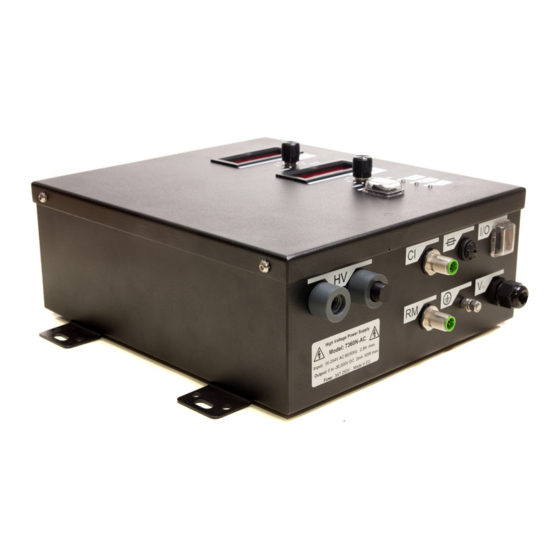
HV outputs. Dry, oil-free location required with ambient temperature of 40° or less. Installation: The enclosure is sealed, but the atmosphere should not be polluted, wet or condensing for high voltage applications. 7 Series Static Generators Iss.1... - Page 8 See page ? 5. General Specification and Dimension Specification of 7 Series Generators: All Models Two HV output connections. External connector boxes can be the number of HV outputs. Model Input HV Max Output Output Local Remote Remote HV & I Power Current...
- Page 9 5. General Specification and Dimensions 7360/7560/73150 & 75150 7360/7560/73150 & 75150 Positioning 7 Series Static Generators Iss.1 The 7 Series Generators should be installed in a clean and dry position. Maxim humidity 70%, non-condensing. Higher levels of humidity affect the process an...
-
Page 10: Positioning
6. Positioning The 7 Series Generators should be installed in a clean and dry position. Maximum humidity 70%, non-condensing. Higher levels of humidity affect the process and can cause tracking in the equipment. It may be mounted horizontally or vertically. Operating Temperature: 0 to 40°C. -
Page 11: Operating And Control
The operation is based on the familiar conventions on standard low voltage power supplies used in laboratories, test houses and general industry. Limits 7 Series Static Generators Iss.1 can be set to the current and voltage levels before the High Voltage (HV) is... - Page 12 7. Operation & Control 7360/7560/73150/75150 The operation is based on the familiar conventions on standard low voltage power supplies used in laboratories, test houses and general industry. Limits can be set to the current and voltage levels before the High Voltage (HV) is turned ON. If limits are not required, then turn both voltage and current potentiometers to maximum before switching HV ON.
- Page 13 HV sockets are needed. If only one HV output is required, HV Outputs: ensure the blanking plug is always fitted to the HV socket not in use. Dirt can penetrate into the H.V Output sockets and cause internal tracking if the blanking plugs are not used. 7 Series Static Generators Iss.1...
- Page 14 7. Operation & Control Control Interface (CI) – All Models A control interface allows for complete remote control and output monitoring of the Generator. A 10V reference supply is provided for complete remote control and ease of use. Connection: 8 Pin M12 Connector. ON-OFF: Remote ON/OFF switching of HV. Output Indicator: HV ON indicator, sinks 15mA, suitable for remote LED or small relay coils.
- Page 15 HIGH VOLTAGE ON: pply. to PIN 1 PIN 4 connected to PIN 1 ing High Voltage. Generator producing High Voltage. to PIN 1 ing High Voltage. nnections nnections 7 Series Static Generators Iss.1 ce - CI :...
-
Page 16: Electrical Connection
8. Electrical Connections Control Interface - CI: Pin 1 White HV On/Off control. OFF: Pin 1 = <0.7V. ON: Pin 1 = 10 - 28V DC. Pin 2 Brown Voltage program, 0-10V = 0-100%, Approx. 100kΩ input impedance. Pin 3 Green Current limit/program, 0-10V = 0-100%. Approx. 100kΩ input impedance. Pin 4 Yellow Voltage sense/readout, 0-10V = 0-100%. 1kΩ Output impedance. Pin 5 Grey Current sense/readout, 0-10V = 0-100%, 1kΩ... - Page 17 This must be connected to an earth / ground. HV Output: Arc fault protected. Ripple at full load: < 0.5% at full load. Voltage rise time: internally limited to 1kV/ms. Voltage fall time: Depends on load. 7 Series Static Generators Iss.1...
- Page 18 The following examples can be used independently or together as required. HV ON/OFF control: 8. Electrical Connections CI Interface Example of Uses The following examples can be used independently or together as required. Generator Front Panel C.I. Remote HV On/Off Input HV ON/OFF control: HV ON/OFF Switch Generator Front Panel ...
- Page 19 HV output voltage. 0 - 10V = 0 - 100% output: Using an external 0-10V FSD ( Full Scale Deflection ) moving coil Voltmeter to monitor actual HV output voltage. 0 - 10V = 0 - 100% output: 7 Series Static Generators Iss.1...
- Page 20 Using a remote 10k Ohm, minimum 100mW, potentiometer to control output curren limit. 8. Electrical Connections setting, 0 - 10V = 0 - 100%: Using an external 0-10V FSD ( Full Scale Deflection ) moving coil Voltmeter to Using an external 0-10V FSD ( Full Scale Deflection ) moving coil Voltmeter to monitor actual HV output voltage.
- Page 21 This takes 5 second after switching off. The Electrode should not be touched during this period as there 7 Series Static Generators Iss.1 will be risk of a small shock.
-
Page 22: Maintenance
This takes 5 seconds after switching off. The Electrode should not be touched during this period as there will be risk of a small shock. Please note: Fraser Generators have no user serviceable parts. The warranty will be void if the customer attempts to make repairs. -
Page 23: Health And Safety
Only suitably qualified and trained personnel should service this equipment. Important: • Use only Fraser Static Generator Electrodes - these are current limited with a resistance between the high voltage and emitters for safety. • The ON OFF switch on the Generator Case must be switched OFF before disconnection of the Bars or undertaking any maintenance. -
Page 24: Troubleshooting
12. Troubleshooting Fault No output, LED’s off and nothing on the output voltage and current display. • Isolate generator from electrical supply. • Check fuse fitted to generator. • Check electrical supply is within specification. • Check supply cable to generator is not damaged. Fault HV output voltage is not reaching set value. - Page 25 Dirty electrode - clean. • Check conductivity of material - if paper it must be >1010 Ohm per Square. Check using a Model 730 SRM. • Material already charged - Neutralise it with a Static Eliminator. 7 Series Static Generators Iss.1...
-
Page 26: Spare Parts And Accessories
13. Spare Parts and Accessories Description Part Number Control Interface M12 x 8 Pin Cable - 5m 80777 Control Interface M12 x 8 Pin Cable - 10m 80978 Remote Monitor M12 x 5 Pin Cable - 5m 80778 Remote Monitor M12 x 5 Pin Cable - 10m 80974 M12 x 4 Pin 24V Power Cable - 5m 80779... - Page 28 For more information about static and to view the full range of our products, please visit www.fraser-antistatic.co.uk Scotts Business Park, Bampton, Devon, GB, EX16 9DN T + 44 (0) 1398 331114 F + 44 (0) 1398 331411 E sales@fraser-antistatic.co.uk W www.fraser-antistatic.co.uk...
Need help?
Do you have a question about the 7 Series and is the answer not in the manual?
Questions and answers