Table of Contents
Advertisement
Available languages
Available languages
Quick Links
NEWTON-L
Barriera a Infrarossi, triplo raggio per esterno,
8 frequenze selezionabili, con disqualifica
Portate 50-100-200 mt
Manuale di installazione
Outdoor triple beam infrared barrier,
8 selectable frequencies, with disqualification
Range 50-100-200 mt
Installation manual
Edizione / Edition 1.2
20MACIE0321
Advertisement
Table of Contents

Summary of Contents for CIAS Elettronica S.r.l. NEWTON-L
- Page 1 NEWTON-L Barriera a Infrarossi, triplo raggio per esterno, 8 frequenze selezionabili, con disqualifica Portate 50-100-200 mt Manuale di installazione Outdoor triple beam infrared barrier, 8 selectable frequencies, with disqualification Range 50-100-200 mt Installation manual Edizione / Edition 1.2 20MACIE0321...
-
Page 2: Table Of Contents
13. AMPIEZZA DEL RAGGIO INFRAROSSO ..............14 14. ALLINEAMENTO OTTICO ...................15 15. ALLINEAMENTO UTILIZZANDO I DIGIT ..............16 16. PREDISPOSIZIONE SENSIBILITA’: VELOCITA’ DI ATTRAVERSAMENTO ....17 17. TEST PRATICO ......................17 18. RICERCA GUASTI.......................18 19. SPECIFICHE TECNICHE ....................19 Manuale di installazione Pagina 1 di 36 NEWTON-L... - Page 3 12. THERMOSTAT RESISTANCES FOR DEMISTING .............31 13. INFRARED BEAM AMPLITUDE ..................31 14. OPTICAL ALIGNMENT ....................32 15. ALIGNMENT USING DIGITS ..................33 16. SETTING SENSITIVITY: CROSSING SPEED ............34 17. PRACTICAL TEST .......................34 18. TROUBLESHOOTING ....................35 19. TECHNICAL SPECIFICATIONS ..................36 Manuale di installazione Pagina 2 di 36 NEWTON-L...
-
Page 4: Introduzione
La serie NEWTON-L dispone di differenti portate (50 – 100 – 200 mt) che devono essere tenute in considerazione durante la fase progettuale. Nelle installazioni multiple, dove più trasmettitori sono orientati verso più... -
Page 5: Trasmettitore
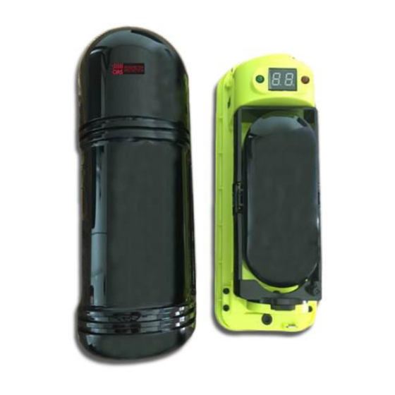
Il Tamper agisce sulla chiusura e apertura del coperchio frontale. 3.2.Funzioni Dip Switch La selezione del canale di trasmissione viene effettuata agendo sui dip switch, posizionati nella parte laterale destra del modulo NEWTON-L. Manuale di installazione Pagina 4 di 36... -
Page 6: Dip Switch
La memorizzazione del canale avviene solo con il dip 7 su ON e dip 8 su OFF, come indicato al par. 3.3.1. Per entrambi i prodotti NEWTON-L e NEWTON-LKIT, i dip switch del trasmettitore sono impostati di default su: Dip 1, 2, 3 → su OFF (Canale 1) Dip 7, 8 →... -
Page 7: Ricevitore
Morsetto 6 = Contatto Comune Relè Disqualifica/Contatto Tamper Morsetto 7 = Contatto NC Contatto Tamper Morsetto 8 = Non Utilizzato Morsetto 9 = Non Utilizzato 4.1.Connessioni Il Tamper agisce sulla chiusura e apertura del coperchio frontale. Manuale di installazione Pagina 6 di 36 NEWTON-L... -
Page 8: Programmazione Canale (7-8)
Il dip 10 seleziona il tipo di contatto dei relè, presenti sul modulo ricevitore. Posizionato su ON, i contatti sono di tipo NO; in posizione OFF, di tipo NC. Per entrambi i prodotti NEWTON-L e NEWTON-LKIT, i dip switch del ricevitore sono impostati di default su: Dip 1, 2, 3 →... -
Page 9: Funzioni Led
Più rapida è la rilevazione del tempo di attraversamento (50mS), minore sarà l’immunità del sistema ai disturbi esterni. La sensibilità maggiore si ottiene ruotando completamente il trimmer in senso orario. Manuale di installazione Pagina 8 di 36 NEWTON-L... -
Page 10: Installazione
CIAS Elettronica S.r.l. Ed. 1.2 6. INSTALLAZIONE E’ possibile installare le barriere NEWTON-L direttamente a parete, oppure su palo. A: fissaggio diretto a muro Rimuovere il coperchio frontale svitando l’apposita vite posta sul fondo del modulo. Utilizzando un cacciavite, sollevare la parte superiore fino alla avvenuta separazione del frontale dal fondo (vedi fig. - Page 11 NOTA: Il palo, su cui viene applicata la ganascia per il fissaggio di staffa e barriera, deve avere un diametro compreso tra 38 e 55 Manuale di installazione Pagina 10 di 36 NEWTON-L...
-
Page 12: Fissaggio Nelle Colonne Tower
NOTA: un esempio pratico di fissaggio a colonna, prevede l’utilizzo di TOWER HT2 (h = 2 mt), con assemblate all’interno, al massimo dell’espandibilità, quattro ottiche (TX o RX) ed un alimentatore NEWTON ALIM. Manuale di installazione Pagina 11 di 36 NEWTON-L... -
Page 13: Precauzioni Per L'installazione
CIAS Elettronica S.r.l. Ed. 1.2 8. PRECAUZIONI PER L’INSTALLAZIONE Manuale di installazione Pagina 12 di 36 NEWTON-L... -
Page 14: Connessioni
La sezione dei cavi di alimentazione, deve essere calcolata in base alla lunghezza della tratta ed alla tipologia di NEWTON-L utilizzata. Per quanto riguarda quella dei conduttori connessi ai contatti di Allarme e Tamper, dipende dal modello e dall’assorbimento della centrale di controllo utilizzata. -
Page 15: Resistenze Termostatate Per Disappannamento
13. AMPIEZZA DEL RAGGIO INFRAROSSO Modello Distanza tra Ottiche Ampiezza diametro fascio IR NEWTON-L50 e NEWTON-LKIT50 50mt Diam. 1,5 mt NEWTON-L100 e NEWTON-LKIT100 100mt Diam. 3,0 mt NEWTON-L200 e NEWTON-LKIT200 200mt Diam. 6,0 mt Manuale di installazione Pagina 14 di 36 NEWTON-L... -
Page 16: Allineamento Ottico
La centratura potrà considerarsi ultimata, nel momento in cui l’ottica posizionata in fronte, sarà riflessa e centrata all’interno del mirino ottico Ripetere le precedenti operazioni anche sull’ottica posizionata di fronte a quella appena regolata Manuale di installazione Pagina 15 di 36 NEWTON-L... -
Page 17: Allineamento Utilizzando I Digit
Nel caso di installazioni multiple, verificare che il livello del segnale, non generato dal proprio trasmettitore infrarosso e ricevuto da ogni singola ottica ricevente, sia inferiore di un valore di almeno 0,5 (Digit), rispetto al livello del segnale rilevato dal trasmettitore corrispondente. Manuale di installazione Pagina 16 di 36 NEWTON-L... -
Page 18: Predisposizione Sensibilita': Velocita' Di Attraversamento
Verificare il corretto rilevamento della condizione di allarme e di conseguenza, il regolare funzionamento. Manuale di installazione Pagina 17 di 36 NEWTON-L... -
Page 19: Ricerca Guasti
Ricercare il massimo allineamento interferenze da altri fonti di emissione possibile infrarossi, ottiche o illuminatori Verificare interferenze da altri trasmettitori infrarossi (rapporto livello segnale proprio/ segnale ottiche adiacenti) Manuale di installazione Pagina 18 di 36 NEWTON-L... -
Page 20: Specifiche Tecniche
CIAS Elettronica S.r.l. Ed. 1.2 19. SPECIFICHE TECNICHE NEWTON-L50 NEWTON-L100 NEWTON-L200 Caratteristiche tecniche NEWTON-L NEWTON-LKIT50 NEWTON-LKIT100 NEWTON-LKIT200 50 mt 100 mt 200 mt Portata massima ESTERNA 150 mt 300 mt 600 mt Portata massima INTERNA Frequenze selezionabili Numero lenti... - Page 21 2. FEATURES NEWTON-L can be used in single installations, in its own case, or in applications requiring multiple infrared barriers to protect a single section of perimeter, with the possibility of pole installation.
- Page 22 3.1. Connections The Tamper acts on front cover closing and opening. 3.2. Dip Switch Functions Transmission channel selection is made via the dip switch located on the right side of the NEWTON-L module. Installation Manual Page 21 of 36 NEWTON-L...
- Page 23 Channels can only be saved when dip 7 is set to ON and dip 8 is set to OFF, as indicated in par. 3.3.1. Transmitter dip switches are set as default to the following for both NEWTON-L and NEWTON-LKIT products: Dip 1, 2, 3 →...
- Page 24 Terminal 6 = Common Contact Disqualification/Tamper Contact Relay Terminal 7 = NC Contact Tamper Contact Terminal 8 = Not used Terminal 9 = Not used 4.1. Connections The Tamper acts on front cover closing and opening. Installation Manual Page 23 of 36 NEWTON-L...
- Page 25 Dip 10 selects the type of relay contact, present on the receiver module. Set to ON, contacts are NO type. In OFF position, they are NC type. Receiver dip switches are set as default to the following for both NEWTON-L and NEWTON- LKIT products: Dip 1, 2, 3 →...
- Page 26 Faster is the crossing time detection (50mS), less is the system will be immune to outside disturbances. Increased sensitivity is obtained by completely turning the trimmer in the clockwise direction. Installation Manual Page 25 of 36 NEWTON-L...
- Page 27 CIAS Elettronica S.r.l. Ed. 1.2 6. INSTALLATION NEWTON-L barriers can be installed directly on walls or on poles. A: direct mounting to walls Remove the front cover by unscrewing the screw located at the bottom of the module. Using a screwdriver, lift the top part until the front separates from the bottom (see fig.
- Page 28 0.5 (Digit) with respect to its received signal level. NOTE: The pole, to which the clamp will be affixed for bracket and barrier mounting, must have a diameter between 38 and 55 mm. Installation Manual Page 27 of 36 NEWTON-L...
- Page 29 NOTE: a practical example of column fastening involves the use of TOWER HT2 (h = 2 mt) with four optics (TX or RX) and a NEWTON ALIM power pack assembled inside at maximum expandability. Installation Manual Page 28 of 36 NEWTON-L...
- Page 30 CIAS Elettronica S.r.l. Ed. 1.2 8. PRECAUTIONS FOR INSTALLATION Installation Manual Page 29 of 36 NEWTON-L...
- Page 31 The power cable cross-section must be calculated based on the length of the section and the type of NEWTON-L used. The cross-section size of conductors connected to Alarm and Tamper contacts depends on the model and on the absorption of the central control unit used.
- Page 32 13. INFRARED BEAM AMPLITUDE Distance between Model IR beam diameter amplitude Optics NEWTON-L50 and NEWTON-LKIT50 50 mt Diam. 1.5 mt NEWTON-L100 and NEWTON-LKIT100 100 mt Diam. 3.0 mt NEWTON-L200 and NEWTON-LKIT200 200 mt Diam. 6.0 mt Installation Manual Page 31 of 36 NEWTON-L...
- Page 33 Repeat the previous operations also on the optics positioned in front of the one just adjusted Installation Manual Page 32 of 36 NEWTON-L...
- Page 34 0.5 (Digit) with respect to the signal level detected by the corresponding transmitter. Installation Manual Page 33 of 36 NEWTON-L...
- Page 35 Once you have completed the preparation of channels, alignment, and sensitivity adjustment, proceed with the practical barrier crossing test to check the effectiveness of the system according to your installation requirements. Verify correct detection of alarm conditions and, as a result, correct operation. Installation Manual Page 34 of 36 NEWTON-L...
- Page 36 Search for maximum possible alignment. from other infrared, optical, or illuminator Check for interferences from other infrared emission sources. transmitters (own signal level/adjacent optical signal ratio) Installation Manual Page 35 of 36 NEWTON-L...
- Page 37 CIAS Elettronica S.r.l. Ed. 1.2 19. TECHNICAL SPECIFICATIONS NEWTON-L50 NEWTON-L100 NEWTON-L200 NEWTON-L technical specifications NEWTON-LKIT50 NEWTON-LKIT100 NEWTON-LKIT200 50 mt 100 mt 200 mt Maximum EXTERNAL range 150 mt 300 mt 600 mt Maximum INTERNAL range Selectable frequencies Number of lenses...
- Page 38 NOTE:...
- Page 39 NOTE:...
- Page 40 Con la presente, CIAS Elettronica, dichiara che questo dispositivo “ NEWTON-L ” è conforme ai requisiti essenziali ed alle altre disposizioni rilevanti della Direttiva 1999/5/CE (Art.3.1 -3.1 -3.2) Hereby, CIAS Elettronica, declares that this device “ NEWTON-L ” is in compliance with the essential requirement and other relevant provisions of Directive 1999/5/EC (Art.3.1...
Need help?
Do you have a question about the NEWTON-L and is the answer not in the manual?
Questions and answers