
Related Manuals for G-Scale Graphics TrackSide

Summary of Contents for G-Scale Graphics TrackSide
- Page 1 Operation and Installation Manual G-Scale Graphics 5860 Crooked Stick Dr. Windsor, CO 80550 970-581-3567 GScaleGraphics@comcast.net www.GScaleGraphics.net Revision C: Updated 6/1/2021 Revision K: Updated 6/1/2021 Page...
-
Page 2: Table Of Contents
Contents Page Overview ………………………………………………………………………….. The Radio System ……………………………………………………………….. The TrackSide R/C Control Board ……………………………….………...….. Installation ……………………………………………………….…….…………. Automated Station Stops ……………………………………………………….. Operation …………………..……………………………………..……….……… Transmitter Command Summary ……………………………………..……….. Trouble Shooting ………………………………….…………...…..……..…….. User Programming …………………………..……..……………………..…… Two Track Operation ……………………………………………………………. Adding Wireless Reed Switch …………………………………………………. -
Page 3: Overview
The Trackside base station can pass up to 10 amps of current from the power supply to your track. That is more than enough to handle one or more locomotives pulling a full train. Typical current draw for one locomotive motor is around 1-2 Amps. -
Page 4: The Radio System
(Toggle Rate) TrackSide R/C operates over a wide range of DC input voltage (7-25V). The power input is protected from dam- age due to reverse polarity, it just won’t operate until the polarity is correct. The output circuitry is protected from short circuits via an easily accessible fuse. -
Page 5: Installation
“DC” output is unregulated and unfiltered. The large AC component of their output may cause damage to the Trackside R/C electronics. If you can measure more than 1 volt AC on the “DC” output of your power pack, it is not suitable! It is assumed that power to the system will be switched on/off at the power supply. -
Page 6: Automated Station Stops
In the event you need to re-learn your TX, you will need to remove the cover on the TrackSide base station. To re-learn, press the Learn button on the TrackSide R/C board. The LED will start blinking. Press and hold the Stop key on the transmitter until the LED stops blinking. -
Page 7: Operation
To enter throttle programming mode, hold the 2nd key, Slower, and Stop buttons down until the LED in the TrackSide base station starts flashing at a fast rate. You will now have full speed control from 0 to 100% power supply voltage. - Page 8 It is doing its job. If you continually blow fuses while simply trying to operate trains, then you can increase the fuse size from the 5 amps, to 7.5 amps, or a maximum of 10 amps. Running with the smallest size fuse that still allows you to operate will provide the best protection for the TrackSide R/C. Page 8...
-
Page 9: Transmitter Command Summary
Press Stop button to exit and save changes at any time. LED will stop flashing. Learn TX - Press the Learn button on the circuit board inside the Trackside box. LED will start flashing. Then press Stop on the transmitter. LED will stop flashing. - Page 10 For two track operation from the same transmitter, both base units need to learn the same transmitter. Learn TX - Press the Learn button on the circuit board inside the Trackside box. LED will start flashing. Then press Stop on the transmitter. LED will stop flashing.
-
Page 11: Trouble Shooting
1) Many low cost train “Power Packs” do not have regulated DC outputs. Their outputs contain a high content of AC voltage that will damage the Trackside R/C unit. It may overheat and burn up the driver stage. If in doubt, please call us. -
Page 12: User Programming
Note: When operating in point-to-point trolley mode, using the reversing magnets, you must have param- eter 3 set for 100%. Otherwise, the loco will run off the end of the track, as the TrackSide will ignore the magnets X% of the time. - Page 13 User Programming. The new option will now be active. Exit Programming Mode To exit programming mode, hold down the Program button for 5 secs, then turn off TrackSide power. To exit programming mode without saving any changes, just turn off TrackSide power.
-
Page 14: Two Track Operation
Converting from One Track One Transmitter Operation Two Tracks on the same Transmitter Operation When you receive your new second base unit, it should be labeled “Track 1”, with Parameter 7 set for Option 2 (Two Track—Left Keys), Parameter 4 set for Option 3 (10 secs Momentum), and new stickers to label your exist- ing transmitter and base unit. -
Page 15: Specifications
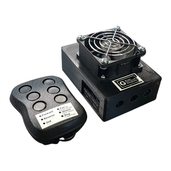
TrackSide R/C - Hardware Specifications 6th Generation Mechanical Enclosure 4.2” X 3.1” X 2.5”H 3D printed ABS or PETG, Black Snap fit between base and cover/fan assembly User Connections: Barrier Strip for Power In, Track Out, accepts 12-22 AWG terminal lugs. -
Page 16: Meanwell Power Supplies
Any 3-wire power cord will work. Set the power input switch on the side of the power supply for 115 VAC U.S. Output voltage should be 24 VDC maximum for use with the G-Scale Graphics Trackside R/C or Track Throttle.
Need help?
Do you have a question about the TrackSide and is the answer not in the manual?
Questions and answers