Table of Contents
Advertisement
Quick Links
INNOVATION IN MOTION
UCM
Installation and set-up guide
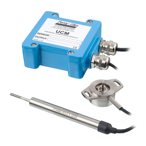
DESCRIPTION
Model UCM is a low voltage DC powered Universal Conditioning Module that can accept a wide range of analogue inductive
transducer types and is suitable to drive LVDTs and RVDTs. For the full product specification, refer to the UCM product
brochure.
MOUNTING
• The UCM module is designed to be mounted on a bulkhead close to the transducer, by using 4 x M5 cap head screws, 28mm
long (minimum) through the mounting holes that are located under the housing lid. The recommended screw tightening torque
is 4Nm.
• The user should also ensure that the rubber seal is properly located in the lid groove prior to re-fitting the lid after setup.
Recommended tightening torque for the lid screws is 2Nm.
WIRING NOTES
• The supply, transducer and output connections are routed through two IP68 rated cable glands that can accommodate cable
diameters of between 3 and 8mm. The user should ensure that the cable glands are tightened sufficiently to ensure cables are
clamped and sealed.
• Users should also ensure adequate sealing of the opposite end connections on supply, transducer and output cables to ensure
moisture cannot migrate down the inside of the cables into the UCM.
• Connections are made to screw terminal blocks on the UCM circuit board.
• The enclosure is not connected internally to ground, so it can be
mounted on a chassis carrying a voltage potential other than
0Vdc.
• If in doubt about wiring to ground, consult your systems
engineer.
• It is essential that correct connections are made before
connecting the power supply. Incorrect connections or
power applied to transducer connection terminals may
destroy the UCM on power-up.
• The UCM module has a supply current requirement of <20mA.
CONNECTIONS
• The UCM, with or without option cards fitted, only requires a
single supply voltage connected between SUPPLY GND and
SUPPLY VPOS.
• When the VM (Voltage Module) option card is used, an internal
negative rail generator enables zero and negative output
voltages to be achieved.
• If you have a dual supply available, you can connect -10V to
-30Vdc to SUPPLY VNEG, in which case the internal negative
supply generator on the VM option card will be disabled and
current will be drawn from the external supply. To obtain
outputs of -10Vdc or -7.5Vdc, the external negative supply must
be at least -13.5Vdc.
• With the lid removed, unscrew the cable glands C1 & C2 (Fig.1).
Pass the power supply/output signal cable through gland C1
into 'SUPPLY' zone on UCM board. Connect the power supply
and output connections to the terminals on the UCM board, as
indicated below and shown in Fig.1.
ZERO ADJUST
ZERO
JP3
JP7
S1+
}
SUPPLY
S1-
P1
P2
LVDT
S2-
S2+
SYNC
GND
JP6
C2
Fig. 1
GAIN ADJUST
GAIN
JP4
VPOS
{
GND
VNEG
GND
OUTPUT
{
IN
OUT
JP1
C1
Advertisement
Table of Contents

Related Manuals for Penny + Giles UCM

Summary of Contents for Penny + Giles UCM
- Page 1 MOUNTING • The UCM module is designed to be mounted on a bulkhead close to the transducer, by using 4 x M5 cap head screws, 28mm long (minimum) through the mounting holes that are located under the housing lid. The recommended screw tightening torque is 4Nm.
- Page 2 Firmly tighten cable gland lock nut C1. • Pass the transducer cable through gland C2 into ‘LVDT’ zone on UCM board. Connect the transducer to the terminals on the UCM board, as indicated below (based on transducer type) and shown in Fig.1.
- Page 3 Switch Position Matrix Guide (Fig.11.), and set the DIP switch positions accordingly. Insert connector of VM card onto the vacant pins of header JP7. Power up the UCM, monitor the voltage output and adjust the zero...
- Page 4 -10V to +10V SETTING THE CURRENT MODULE (CM) CARD • When the UCM is fitted with the current module, the output load (resistive to 0V line) needs to be 20 ohms minimum, 400 ohms maximum for optimum linearity. • When the Current Module (CM) output option card is selected, there are no user-configurable options on the card. Insert connector of CM card onto the vacant pins of header JP7.
Need help?
Do you have a question about the UCM and is the answer not in the manual?
Questions and answers