Table of Contents
Advertisement
Quick Links
Installation and Operation Manual
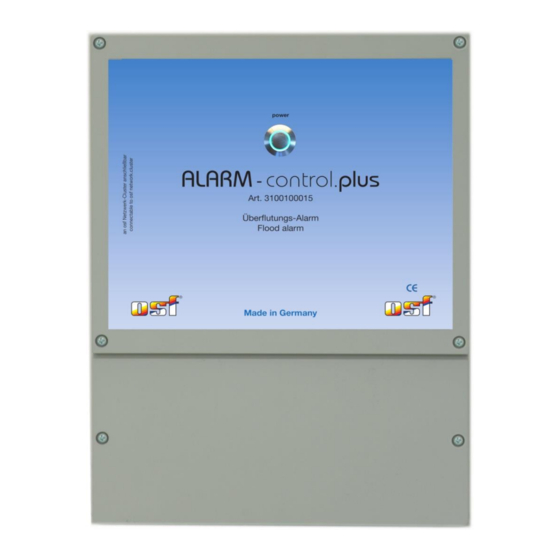
Alarm-control.plus
Dimensions:
Operating voltage:
Power consumption:
Load capacity of the potential-free contact:
Switching capacity of the 230V output:
Protection class:
Number of inputs for water sensors:
Operating voltage of the water sensors:
Climate sensor input:
Ambient temperature:
Air humidity:
Leak warning device
with integrated webserver
Technical data
220mm x 285mm x 80mm
230V/50Hz
max. 8A (230V)
max. 4A (AC1)
12V AC (SELV)
digital sensor system „Klima 2"
0-40°C
0-95% non condensing
<10 W
IP 40
6
Advertisement
Table of Contents

Summary of Contents for OSF Alarm-control.plus
- Page 1 Installation and Operation Manual Alarm-control.plus Leak warning device with integrated webserver Technical data Dimensions: 220mm x 285mm x 80mm Operating voltage: 230V/50Hz Power consumption: <10 W Load capacity of the potential-free contact: max. 8A (230V) Switching capacity of the 230V output: max.
-
Page 2: Table Of Contents
Alarm-Control.plus can work independently or as an extension unit for the PC-45-exclusiv system. Up to 6 water sensors can be connected to the Alarm-control.plus unit. Suitable sensors are pairs of immersion electrodes or float switches. A climate sensor can optionally be connected to the device, which enables the air temperature and humidity in the technical room to be monitored. -
Page 3: General Instruction
With the colored illuminated button on the front of the housing you can: a) Switch off the Alarm-control.plus. The device is switched off by pressing the button for 3 seconds. When the device is switched off, the button does not light up and the device does not respond to leak sensors. -
Page 4: Connection Of The Water Sensors
A standard network cable (patch cable, CAT5) must be used for the connection. Each device in a network cluster (PC-45 exclusiv,Alarm-control.plus etc.) must be in the same local network. The easiest way is to connect all devices to a network switch. Our product range includes a suitable network switch named “Cluster-switch.plus”. -
Page 5: Connection To The Pool Control Pc-45 Exclusiv
Smart-Touch control panel, go to the “Add OSF device” menu and select the “Alarm-control.plus” block. Then press the start button and then the LAN button in the Alarm-control.plus according to the instructions displayed. For more information, see the instructions for the external smart touch control panel. -
Page 6: Setup And Configuration
Installation and operating manual for Alarm-control.plus page 6 (10) Setup and configuration The configuration and setting of the Alarm-control.plus device can be done via the screen of the PC-45 exclusiv, from the computer or smartphone. Configuration from the PC-45 exclusiv After the two controls have been connected, an additional symbol appears in the main menu of the PC-45 exclusiv. -
Page 7: Connect To A Computer Network And The Internet
7 (10) Connect to a computer network and the Internet The Alarm-control.plus has a LAN connection (RJ-45, Ethernet) and supports the Fast Ethernet protocol with a speed of up to 100 Mbit / s. Below is a typical diagram for connection of the Cover-control.plus to a computer network that enables access to the device parameters both from the local network and via the global Internet. -
Page 8: Webserver
Installation and operating manual for Alarm-control.plus page 8 (10) Webserver The web server creates HTML pages for Alarm-control.plus and sends them to the internet browser of a computer or smartphone on request. The integrated web server enables remote monitoring of the sensors from any computer or smartphone. -
Page 9: Climate Sensor Configuration
This parameter determines how long the alarm pause lasts when you press the button on the front of the Alarm-control.plus. After the pause time has elapsed, the device automatically returns to the active mode. The button‘s illumination is blue during the pause. -
Page 10: Wiring Diagram
Installation and operating manual for Alarm-control.plus page 10 (10) Wiring diagram Alarm-Control.plus 10 11 12 13 motor- ALARM mains signal contact valve 1/N/PE Up to 6 water sensors of different types: potential-free 230V 50Hz 230V max. 8А max. 4А water sensor...


Need help?
Do you have a question about the Alarm-control.plus and is the answer not in the manual?
Questions and answers