Table of Contents

Summary of Contents for Jesco GW 601
- Page 1 GW 601 Gas Warning Device for Chlorine Gas, Chlorine Dioxide and Ozone Operating instructions Read this operating manual before using the equipment. To be retained for future reference. Dosing Liquids Conveying Gases Control Systems...
-
Page 2: Table Of Contents
12.5 Power supply backup system (accessory) ......................22 12.6 Disposal ................................ 22 13. Troubleshooting ..............................23 14. Spare parts ................................24 Device revision ................................24 Index.....................................25 Warranty Application ..............................26 CE Declaration of conformity ............................27 2 | Operating Manual GW 601 | Table of Contents... -
Page 3: General And Safety Instructions
Do not bury cord. Secure the cable to avoid damage by lawn mowers, hedge trimmers and other equipment. WARNING! To reduce the risk of electric shock, replace the cable immediately if damaged. Safety notices | Operating Manual GW 601 | 3... -
Page 4: Hazards Due To Non-Compliance With The Safety Instructions
No liability can be accepted for any damage resulting from the use of non-Lutz-Jesco parts. Use only the manufacturer's spare parts and sensors. Otherwise the warranty is invalidated. 4 | Operating Manual GW 601 | Safety notices... -
Page 5: Before Using The Equipment
GW 601 gas warning device for chlorine dioxide, 0…2 ppm 23600221 GW 601 gas warning device for ozone, 0…1 ppm 23600222 GW 601 gas warning device for ozone, 0…2 ppm Before using the equipment | Operating Manual GW 601 | 5... -
Page 6: Functional Range
The electronic system of the CM 601 transmitter records the sensor signal and converts it into an impressed current of 4 – 20 mA which is transmitted to the GW 601 gas warning device. The 4 … 20 mA signal is evaluated in the gas warning system GW 601 and displayed as chlorine content in the air. If the alarm thresholds set have been exceeded, alarm conditions are displayed or relays switched to notify the relevant persons. -
Page 7: Dimensioned Drawings
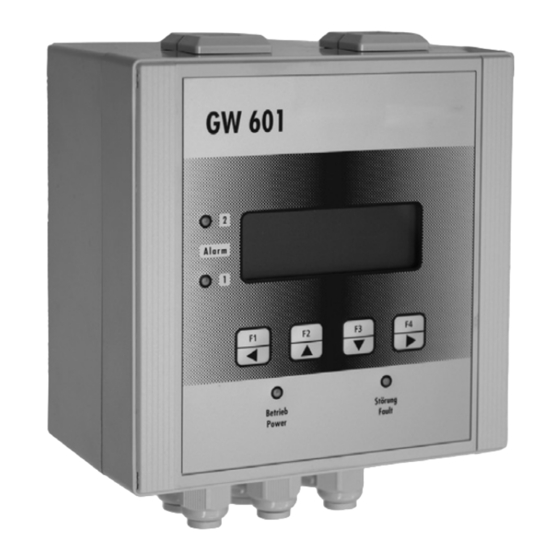
4. Dimensioned drawings 90 mm 160 mm 146 mm Fig. 4.1: Gas warning device GW 601 105 mm 65 mm Fig. 4.2: Transmitter Fig. 4.3: Power supply backup system (accessory) Dimensioned drawings | Operating Manual GW 601 | 7... -
Page 8: Technical Data
1x M20 x 1.5 (cable diameter 7 … 13 mm) 5x M16 x 1.5 (cable diameter 5 … 10 mm) Connections Screw-type terminals for cables up to maximum 1.5 mm Ambient temperature -10 … +40 °C 8 | Operating Manual GW 601 | Technical data... - Page 9 2 years, depending on the operating conditions Self-monitoring If an error is detected during the automatic checks, the output current is set to 1.1 mA. The yellow LED indicates a fault on the GW 601 gas warning device. IMPORTANT! Avoid prolonged operation in dry atmospheres. Permanent exposure to H S will damage the sensor.
- Page 10 Air humidity 0 … 90 % rH, non-condensing Housing Steel sheet, powder-coated, lockable Dimensions (W x H x D) 380 x 380 x 210 mm Protection class IP 66 Weight approx. 18 kg 10 | Operating Manual GW 601 | Technical data...
-
Page 11: Assembly And Installation
47 nF 260 V 22 Ohm 2 Watt < 150 mA 100 nF 260 V 47 Ohm 2 Watt < 1 A 220 nF 260 V 47 Ohm 2 Watt Assembly and installation | Operating Manual GW 601 | 11... -
Page 12: Transmitter
When assembling make sure there is clear access to the device. 6.2 Transmitter • A transmitter can be connected to the GW 601 gas warning device. • The transmitter is connected via a shielded 3-wire cable. •... - Page 13 I out - 4 … 20 mA output I out + 485A A (-) RS 485 interface 485B B (+) Fig. 6.1: GW 601 gas warning system wiring diagram, a Connection to transmitter SENS ZERO LED (GN) LED (RD) Terminal Function Connection...
-
Page 14: Drill Template
6.4 Drill template Width x height Gas warning device GW 601 146 x 146 mm Transmitter 52 x 113 ... 116 mm 14 | Operating Manual GW 601 | Assembly and installation... -
Page 15: Operation
4. line: Assignment of the function keys F1 to F4. Function keys Normal mode Activation / service mode Jump to menu (NEXT) ▲ and ▼, modify figures / scroll through selection Acknowledge alarms Not assigned Confirm entry Operation | Operating Manual GW 601 | 15... -
Page 16: Configuration
The changes are only activated once the menu has been exited. If you exit the menu without pressing F4 (SAVE), the most recent settings remain intact. If no input is made for more than 10 minutes, the GW 601 reacts differently, depending on the operating mode: •... - Page 17 ACTUAL: The current, unconverted value of the transmitter output current at the input of the gas warning device is displayed. ATTENTION! The following adjustment to the GW 601 gas warning system without a transmitter must only be per- formed by trained personnel. Zero Zero point position.
-
Page 18: Operation
Integrated signal generator *) LEDs and relays switch according to the limit exceeded **) LEDs and relay switch if there is a fault with the GW 601 gas warning device or transmitter. 18 | Operating Manual GW 601 | Operation... -
Page 19: Relays
10.2 Configuration Direction The relays in the GW 601 gas warning device can work according to two different principles. They can be adjusted in the Relay Mode menu. Relays | Operating Manual GW 601 | 19... -
Page 20: Analogue Output And Interface
The analogue output corresponds to the measuring signal from the transmitter provided it lies within the 1.5 … 22.5 mA range. 11.2 Interface The devices can be optionally fitted with RS 485 and RS 232 interfaces. These are for service purposes only. 20 | Operating Manual GW 601 | Relays... -
Page 21: Maintenance
12. Maintenance Regular inspection and functional testing must be carried out on the supplied GW 601 measuring, monitor- ing and warning system at maximum 6-monthly intervals. National regulations or local standards may also apply. Proper maintenance is the responsibility of the system's operating company. The results of the maintenance work should be documented if this is not already required by the prevailing regulations. -
Page 22: Functional Check
The equipment was manufactured in accordance with the ROHS guideline and the waste electrical equip- ment legislation. The manufacturer will take care of disposal if the equipment is returned free of charge. It should not be disposed of as domestic waste! 22 | Operating Manual GW 601 | Maintenance... -
Page 23: Troubleshooting
13. Troubleshooting WARNING! If the GW 601 gas warning device indicates a fault that the operating company cannot rectify immediately, appropriate measures must be taken and the maintenance service department notified. Apply warning notices and notify personnel about the situation until the fault is rectified. -
Page 24: Spare Parts
It contains all the technical information required for installation, start-up and maintenance. Should you have any questions or require further information regarding this operating manual, please contact the manufac- turer or its official national representative. 24 | Operating Manual GW 601 | Spare parts... -
Page 25: Index
Internal fuse ............8, 22 Voltage supply ..............8 Limit Value..............19 Warranty claim..............26 Wiring diagram .............12 Maintenance ..............21 Measuring gas ..............6 Measuring principle ............9 Measuring range .............9 Operating state .............18 Operation ..............15, 18 Part numbers ..............5 Index | Operating Manual GW 601 | 25... -
Page 26: Warranty Application
Accessories used if any: ......................................................................................................Commissioning (date): ..............................Running time (approx. operating hours): ........................... Please indicate the specific features of the installation and enclose a simple sketch showing materials, diameters, lengths and heights. 26 | Operating Manual GW 601 | Warranty claim... -
Page 27: Ce Declaration Of Conformity
(PT) Certificado de conformidade da UE Os abaixo mencionados Lutz-Jesco GmbH, Am Bostelberge 19, 30900 Wedemark, por este meio certificam que ao sair da fábrica o aparelho abaixo mencionado está de acordo com as directrizes harmonizadas da UE, padrões de segurança e de produtos específicos. Este certificado ficará...