Table of Contents
Advertisement
Available languages
Available languages
Advertisement
Chapters
Table of Contents

Related Manuals for TIP SPF 180 E


Summary of Contents for TIP SPF 180 E
- Page 1 SPF 180 E Originalgebrauchsanweisung – Sandfi lteranlage Translation of original operating instructions – Swimming Pool Filter Set Az eredeti használati útmutató fordítása – Medence szűrőkészlet Tłumaczenie oryginalnej instrukcji obsługi – Zestaw fi ltacyjny do basenu...
- Page 2 Normen: Schwimmbadfilter Set EN 55014-1:2006 + A1:2009 + A2:2011 Swimming Pool Filter Set EN 55014-2:2015 EN 61000-3-2:2014 EN 61000-3-3:2013 SPF 180 E EN 62233:2008 EN 60335-2-41:2003 + A1:2004 + A2: 2010 EN 60335-1:2012 + A11:2014 EN 50581:2012 Dokumentationsbevollmächtigter: Peter Haaß...
-
Page 3: Table Of Contents
Vor Inbetriebnahme bitte unbedingt die Gebrauchsanweisung lesen Liebe Kundin, lieber Kunde, Herzlichen Glückwunsch zum Kauf Ihres neuen Gerätes von T.I.P.! Wie alle unsere Erzeugnisse wurde auch dieses Produkt auf der Grundlage neuester technischer Erkenntnisse entwickelt. Herstellung und Montage des Gerätes erfolgten auf der Basis modernster Pumpentechnik und unter Verwendung zuverlässigster elektrischer bzw. -
Page 4: Technische Daten
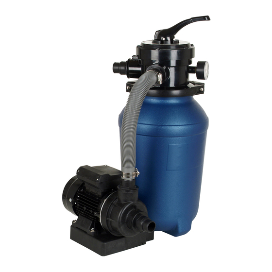
2. Technische Daten Modell SPF 180 E Netzspannung / Frequenz Pumpe 220-240 V~ / 50 Hz Nennleistung P1 / P2 250 Watt / 180 Watt Schutzart IPX5 Durchfluss Sandfilter 4.500 l/h Max. Fördermenge (Q 7.900 l/h Max. Druck 0,6 bar Gewindeanschluss 45,48 mm (1½"... -
Page 5: Installation
Arbeitsweise des Sandfilter Sets Das einströmende Wasser wird über das 4-Wege-Ventil in den oberen Teil der Sandfilterfüllung geleitet. Auf sei- nem Weg durch die Sandfilterfüllung werden Schmutz und Fremdkörper im Filterbett zurückgelassen. Das gefil- terte Wasser gelangt vom unteren Teil des Sandfilterbehälters über ein Ausströmrohr durch das 4-Wege-Ventil wieder in das Schwimmbecken. - Page 6 Hängen Sie den Sandfilterbehälter so in die Grundplatte der Pumpe ein, dass die Ablassöffnung des Filter- behälters nach außen zeigt (Abb.3). Abb. 3 Bauen Sie nun das Ausströmrohr mit dem unteren Filtertopf von oben in den Sandfilterbehälter ein. Dann le- gen Sie den Einfülltrichter auf die obere Öffnung des Behälters.
- Page 7 Verbinden Sie den Sandfilterbehälter mit dem Schlauch, den Schlauchklemmen und Schlauchanschlüssen. (Abb. 6) Abb. 6 Beachten Sie folgende Hinweise zur Installation 1. Falls die Pumpe, wie empfohlen, unterhalb des Wasserstandes installiert wird, sollte ein Absperrventil einge- baut werden. Dies verhindert einen Wasserfluss bei Wartungsarbeiten. 2....
-
Page 8: Elektrischer Anschluss
Zulauf der Pumpe (Pump) Ablauf zum Schwimmbecken (Pool) für Filterbetrieb Ausgang für Abwasser (Waste) für Rückspülen Manometer Abb. 7. Stellen Sie sicher, dass immer ausreichend Wasser im Sandfiltertank ist, bevor Sie starten. Wenn die Pumpe nicht läuft, beachten Sie die Hinweise im Abschnitt Fehlersuche / Ratschläge. Stellen Sie sicher, dass alle Saug- und Auslassventile geöffnet sind, bevor Sie die Pumpe starten, andernfalls wird dies zu Schäden an der Pumpe führen (s. -
Page 9: Inbetriebnahme
8. Inbetriebnahme Während des Betriebs der Pumpe dürfen sich keine Personen im Wasser aufhalten. Die Pumpe darf nur in dem Leistungsbereich verwendet werden, der auf dem Typenschild ge- nannt ist. Das Trockenlaufen - Betrieb der Pumpe, ohne Wasser zu fördern - muss verhindert werden, da Wassermangel zum Heißlaufen der Pumpe führt. -
Page 10: Wartung Und Pflege
Nachspülen (Rinse) – Nach dem Rückspülen wählen Sie bei ausgeschalteter Pumpe die Position Nachspülen. Schalten Sie die Pumpe erneut an und lassen Sie sie für ca. 1 Minute laufen. Dadurch wird der Schmutz aus dem Rückspülvorgang aus dem Filter gewaschen und ein möglicher Rückfluss in das Schwimmbecken verhindert. Schalten Sie dann die Pumpe wieder aus, setzen das Ventil auf Position FILTER und starten die Pumpe für den normalen Filterbetrieb. - Page 11 TÖRUNG ÖGLICHE RSACHE EHEBUNG 2. Der Motor läuft, Das Pumpengehäuse ist nicht mit Stellen Sie sicher, dass der Wasserstand aber die Pumpe Flüssigkeit befüllt. im Becken oberhalb des Saugpunktes ist. fördert keine Stellen Sie sicher, dass Siebe frei von Flüssigkeit. Schmutz sind.
-
Page 12: Garantie
12. Bestellung von Ersatzteilen Die schnellste, einfachste und preiswerteste Möglichkeit, Ersatzteile zu bestellen, erfolgt über das Internet. Unse- re Webseite www.tip-pumpen.de verfügt über einen komfortablen Ersatzteile-Shop, welcher mit wenigen Klicks eine Bestellung ermöglicht. Darüber hinaus veröffentlichen wir dort umfassende Informationen und wertvolle Tipps zu unseren Produkten und Zubehör, stellen neue Geräte vor und präsentieren aktuelle Trends und Innova-... - Page 13 Abb. 8 Position Teile Nr. Beschreibung Menge 72140 4-Wege Ventil 72141 Spannring 72142 O-Ring 70790 Sandfilterbehälter 72144 Ausströmrohr mit Filterkorb 72145 Ablassfilter 70792 Grundplatte 72147 Schrauben M6*25 und Muttern M6 72148 O-Ring 72149 Schlauchanschluss 72150 Schlauchschelle 72151 32 mm (1¼″)*35 cm Verbindungsschlauch 72152 Pumpe (220-240V~ / 50 Hz) komplett 72153...
-
Page 14: Service
Fax: + 49 (0) 7263 / 9125 25 Siemensstraße 17 E-Mail: service@tip-pumpen.de D-74915 Waibstadt Eine aktuelle Bedienungsanleitung als PDF-Datei kann bei Bedarf per E-Mail unter: service@tip-pumpen.de an- gefordert werden. Nur für EU-Länder Werfen Sie Elektrogeräte nicht in den Hausmüll! Gemäß Europäischer Richtlinie 2012/19/EU über Elektro- und Elektronik-Altgeräte und Umset- zung in nationales Recht müssen verbrauchte Elektrogeräte getrennt gesammelt und einer um-... - Page 15 Strictly ensure that you have read the use instructions before placing the pump in service! Dear customer, Congratulation for buying your new device from T.I.P.! Like all our products, this one, too, was developed using the latest technological knowledge. The device was manufactured and assembled on the basis of state-of-the-art pump technology using most reliable electrical or electronic components which ensure a high level of quality and a long life of your new product.
-
Page 16: Technical Data
2. Technical data Model SPF 180 E Mains voltage / frequency 220-240 V~ / 50 Hz Performance P1 / P2 250 Watt / 180 Watt Protection class IPX5 Flow rate through sand filter 4,500 l/h Max. delivery height (Q 7,900 l/h Max. -
Page 17: Scope Of Delivery And Optional Accessories
5. Scope of delivery and optional accessories This product includes: A sand filter tank including base plate, 4-way valve, one pump, two bags with connection and installation accesso- ries (see chapter 6 "Installation"), an instruction manual. Check the contents for completeness. If possible, keep the packaging until the end of the warranty period. Dis- pose of packaging materials in an environmentally sound manner. - Page 18 Install the drain plug assembly to sand tank as below pictures. (fig. 2) fig. 2 Mount the sand filter container into the base plate of the pump so that the discharge opening of the filter con- tainer points outwards (fig. 3). fig.
- Page 19 Remove the funnel and clean the edge of the container opening carefully sand residues. To facilitate the start-up, it is recommended to fill the sand filter tank to ¾ with water. Then mount the 4-way valve and the fil- ter gasket (O-ring, Fig. 5) The connection is made with a clamping ring. The clamping ring is screwed to the clamping ring screw and clamping ring nut.
-
Page 20: Electrical Connection
1. inlet from the pump (marked “pump”) 2. outlet to the swimming pool (marked “pool”) for normal filter operation 3. outlet for waste water (marked „waste“) for back wash 4. pressure gauge fig. 7 Make sure, there is sufficient in the sand filter tank before priming the pump If the pump does not prime, please observe the notes in the section trouble shooting. - Page 21 pump pull out the power cord and let the system cool down. The floating ring seals can be damaged if the pump is running dry and should be replaced if this happened. Do not expose the pump to rain or humidity. Avoid any dripping connectors. Do not place the pump in a wet or humid environment.
-
Page 22: Maintenance And Care
9. Maintenance and care Prior to carrying out any maintenance work, the pump must be separated from the electrical mains. If you fail to separate the unit from mains, there is a risk of an inadvertent start of the pump. We decline any liability for damage caused by inappropriate repair attempts. - Page 23 ALFUNCTION OSSIBLE AUSE LIMINATION 2. The motor is run- The pump housing is not filled with liquid. Ensure the water level in the pool is above ning, but the pump the suction point of the pump. Make sure is not discharging the strainer is free of dirt any liquid.
-
Page 24: Warranty
12. How to order spare parts The fastest, most simple and cheapest way of ordering spare parts is through the internet. On our www.tip- pumpen.de website you will find a convenient spare part shop where you can order spare parts with just a couple of clicks. - Page 25 Fig. 8 Position Part No. Description Quantity 72140 Lid with 4 position valve 72141 Flange clamp set 72142 o-ring 70790 Sand filter tank 72144 Tube with filter basket 72145 Drain plug 70792 Sand filter support 72147 Screws M6*25 and nut M6 72148 O-ring 72149...
-
Page 26: Service
13. Service In the case of warranty claims or malfunction, please contact your point of sale. A current operating manual is available as required as a PDF file via e-mail: service@tip-pumpen.de. For EC countries only Please do not dispose of electrical appliances in the regular domestic waste! - Page 27 Üzembe helyezés előtt feltétlenül olvassa el a használati útmutatót! Kedves vásárló, Gratulálunk új T.I.P. berendezése megvásárlásához! Mint termékeink mindegyike, ez is a legújabb műszaki ismereteket alapul véve készült. A gép gyártása és összeszerelése is a legmodernebb szivattyú technika alapján történt, a legmegbízhatóbb villamos illetve elektronikus alkatrészek felhasználásával, így garantált új szerzeményének magas minősége és hosszú...
-
Page 28: Helyzet És Működtetés
át a 4-utas szelepen keresztül visszakerül a medencébe. 3. Műszaki adatok Modell SPF 180 E Szivattyú hálózati feszültsége / frekvenciája 220-240 V~ / 50 Hz Névleges teljesítmény P1 / P2 250 Watt / 180 Watt Védelmi mód... -
Page 29: Alkalmazási Terület
4. Alkalmazási terület Ez a szűrőkészlet a medence vizének tisztítására való. Ezt a készüléket magánhasználatra fejlesztettük ki, nem ipari vagy kereskedelmi célokhoz. 5. Telepítés 5.1. Általános útmutatók a telepítéshez A készüléket a telepítés időtartama alatt nem szabad a villamos hálózatra csatlakoztatni. - Page 30 3. Nyomja rá a homokszűrő tartályát az alaplapra és tekerje el, hogy a leeresztőszűrő kifelé (3. ábra) mutasson. ábra 3 4. Ekkor szerelje össze a kiáramlócsövet az alsó szűrőedénnyel felülről a homokszűrőtartályba. Ezután a betöltőtölcsért helyezze a tartály felső nyílására. Töltse fel ekkor a tartályt kvarchomokkal (homok tömege 13 kg).
- Page 31 Kösse össze a homokszűrő tartályát a tömlővel, a tömlőbilincsekkel és -csatlakozókkal. (6. Ábra) ábra 6 Tartsa be a telepítés következő utasításait. 1. Győződjön meg arról, hogy a szűrő nyomás alatt áll. Használjon egy túlnyomásszelepet, mikor a berendezés a ház vízművéhez csatlakozik. 2....
-
Page 32: Villamos Csatlakozás
Győződjön meg arról, hogy a homokszűrő tartályában mindig elegendő víz van, mielőtt elindítja. Ha a szivattyú nem szív, nézze meg a Hibakeresés fejezetben lévő tanácsokat. Üzembe helyezéskor ellenőrizze, hogy minden szívó és leeresztőszelep nyitva van-e a szivattyú indítása előtt, különben megsérülhet. 5.4. - Page 33 A szivattyú nem működhet, ha a befolyónyílása be van zárva. Szigorúan tilos a szivattyú nyílásába belenyúlni, mikor a készülék az áramellátó hálózathoz csatlakozik. A szivattyút minden használat előtt alaposan szemlélje meg. Ez különösen érvényes a hálózati csatlakozó vezetékre és a hálózati dugaszra. Figyeljen a csavarok rögzítésére és minden csatlakozás kifogástalan állapotára.
-
Page 34: Hibakeresés/Tanácsok
Utánöblítés (Rinse) Az utánöblítés végeztével kikapcsolt szivattyú mellett válassza ki az Utánöblítés helyzetet. Kapcsolja vissza a szivattyút, és körülbelül 1 percig hagyja járni. Ezzel kimossa a szűrőből a szennyeződést, és megakadályozza, hogy visszafolyjon a medencébe. Ezután ismét kapcsolja ki a szivattyút, állítsa a szelepet FILTER helyzetbe, és indítsa el a szivattyút a normál működésben. -
Page 35: Garancia
HIBA LEHETSÉGES OKA MEGSZÜNTETÉSE A szivattyú nem szállít Nincs áram. 1.GS-minősítésű készülékkel ellenőrizzük, hogy van- folyadékot, a motor nem e feszültség (vegyük figyelembe a biztonsági működik. utasításokat!). Ellenőrizzük, hogy a csatlakozó dugó rendesen be van-e dugva. Bekapcsolt a termikus motorvédelem. A szivattyút válassza le a hálózatról, hagyja lehűlni, és szüntesse meg az okot. -
Page 36: Alkatrészek Rendelése
11. Alkatrészek rendelése Alkatrészeket leggyorsabban, legegyszerűbben és legolcsóbban az interneten át lehet rendelni. A honlapunk www.tip-pumpen.de rendelkezik komplett alkatrész áruházzal, ahol néhány kattintással intézhető a rendelés. Ezen kívül ott hozunk nyilvánosságra információkat és értékes tippeket adunk a termékeinkkel és a tartozékokkal kapcsolatban, új berendezéseket mutatunk be és az aktuális trendekről és innovációkról is tájékoztatjuk a szivattyú... -
Page 37: Szerviz
Ábra 9 12. Szerviz Garanciális igények vagy működési zavarok esetén keresse fel a vásárlás helyét an. Szükség esetén az aktuális kezelési útmutató pdf-változatát a service@tip-pumpen.de e-mail címen igényelheti. Csak EU-országok számára Elektromos készüléket soha ne dobjon a háztartási hulladék közé! A 2012/19/EU számú, az elektromos és elektronikai berendezések hulladékaival... - Page 38 Przed uruchomieniem należy koniecznie przeczytać instrukcję użytkowania! Szanowny Kliencie! Gratulujemy zakupu nowego urządzenia firmy T.I.P.! Produkt ten, jak wszystkie nasze wyroby, opracowano wg najnowszych osiągnięć techniki. Produkcja i montaż niniejszego urządzenia są zgodne z nowoczesnymi rozwiązaniami techniki pomp, wykorzystano tu niezawodne elektryczne, elektroniczne i mechaniczne podzespoły, które gwarantują wysoką...
-
Page 39: Położenie I Działanie
ignorowanie tego ostrzeżenia wiąże się z zagrożeniem zdrowia użytkownika i jego własności. Nieprzestrzeganie niniejszej instrukcji związane jest z ryzykiem porażenia prądem elektrycznym, które może doprowadzić do obrażeń u osób i/lub szkód materialnych Sprawdź, czy urządzenie nie uległo uszkodzeniu podczas transportu. W przypadku stwierdzenia uszkodzeń... -
Page 40: Dane Techniczne
4. Dane techniczne Modell SPF 180 E Napięcie sieciowe / częstotliwość pompy 220-240 V~ / 50 Hz Moc znamionowa P1 / P2 250 Watt / 180 Watt Stopień ochrony IPX5 Przepływ filtra piaskowego 4.500 l/h Maks. wydajność pompy (Q 7.900 l/h maks. - Page 41 5.2. Instalacja filtra piaskowego 1. Przymocować pompę do płyty bazowej, jak pokazano na rys. 1 Rys. 1 2. Zainstalować filtr spustowy przy zbiorniku filtra piaskowego w sposób przedstawiony na rysunkach. (Rys. 2) Rys. 2 3. Wcisnąć zbiornik filtra piaskowego w płytę podstawy i obrócić go w taki sposób, aby filtr spustowy był...
- Page 42 4. Zamocować rurę wylotową z dolną czaszą filtra, wkładając ją od góry do zbiornika filtra piaskowego. Następnie założyć lejek napełniający na górny otwór zbiornika. Napełnić zbiornik piaskiem kwarcowym (ciężar piasku 13 kg). Piasek nie może dostać się do rury wylotowej. (Rys.
- Page 43 zamontować zawór odcinający. Zapobiega on przepływowi wody podczas prac konserwacyjnych. 3. Unikać zbędnych złączek i zagięć węża. Krótsza droga do pompy zwiększa efektywność. 4. Połączenia śrubowe powinny być wolne od rozpuszczalników, w przeciwnym razie mogą one oddziaływać na o-ring i uszczelnienia, powodując ich uszkodzenie. 5....
-
Page 44: Podłączenie Pompy Do Sieci Elektrycznej
6. Podłączenie pompy do sieci elektrycznej Urządzenie posiada kabel przyłączeniowy z wtyczką sieciową. W celu uniknięcia zagrożeń, zlecaj wymianę kabla przyłączeniowego i wtyczki wyłącznie wykwalifikowanym elektrykom. Nigdy nie przenoś pompy trzymając jej za kabel. Nie ciągnij również nigdy za kabel w celu wyciągnięcia wtyczki sieciowej z gniazdka. -
Page 45: Konserwacja
W przypadku przeciążenia silnik wyłączy się samoczynnie i włączy się ponownie, gdy odzyska odpowiednią temperaturę. Ewentualne przyczyny zakłóceń pracy i wskazówki dotyczące ich usunięcia opisano w ustępie „Konserwacja i pomoc w przypadku zakłóceń pracy”. Wskazówki, których należy przestrzegać podczas pierwszego uruchamiania Przed zmianą... -
Page 46: Wyszukiwanie Błędów / Porady
Nie odpowiadamy za uszkodzenia spowodowane niefachowymi próbami naprawy urządzenia. Szkody będące następstwem niefachowych prób naprawy pompy powodują wygaśnięcie gwarancji. Regularna konserwacja i dbanie o sprzęt zmniejszają niebezpieczeństwo ewentualnych zakłóceń pracy i przyczyniają się do przedłużenia żywotności pompy. Użytkownicy powinni upewnić się, że prace konserwacyjne są wykonywane przez wykwalifikowane osoby, które w pierwszej kolejności starannie przeczytały instrukcje dotyczące instalacji i konserwacji. -
Page 47: Gwarancja
Zakłócenie w pracy Prawdopodobna przyczyna Usunięcie Silnik pracuje, ale pompa nie Obudowa pompy nie została Upewnić się, że poziom wody w basenie tłoczy cieczy. napełniona cieczą. znajduje się powyżej punktu zasysania. Upewnić się, że sita nie są zanieczyszczone. Napełnić kadłub pompy cieczą (patrz punkt „Uruchamianie”). -
Page 48: Zamawianie Części Zamiennych
Przestrzeganie wskazówek dotyczących instalacji i konserwacji urządzenia podanych w niniejszej instrukcji zasadniczo przyczynia się do wydłużenia żywotności części podlegających naturalnemu zużyciu. W przypadku zgłoszenia reklamacji zastrzegamy sobie prawo do naprawy uszkodzonych części, bądź wymiany części lub całego urządzenia. Wymienione części przechodzą na naszą własność. Wyklucza się... -
Page 49: Serwis
12. Serwis W przypadku zgłoszeń reklamacyjnych lub /i napraw pogwarancyjnych prosimy zwracać bezpośrednio Dystrybutor: Serwis: T.I.P. Polska Sp. z o.o. PPHU TECH-MIG ul. Warszawska 164, 05-082 Latchorzew ul. Kaczorowa 26A, 03-046 Warszawa Polska Polska Tel.: (+48) 22 211 80 11 Tel.: (+48) 601 380 587, 22 427 58 30 e-mail: info@tippolska.pl e-mail: serwis@techmig.pl... - Page 50 Notizen / notes / note / notas...
- Page 51 Notizen / notes / note / notas...
- Page 52 Sollten Sie technische Fragen oder Probleme bei der Inbetriebnahme haben, können Sie uns gerne unter folgenden Telefonnummern kontaktieren: SERVICE-HOTLINE +49 (0) 7263 9125-0 Montag bis Freitag von 08.00 bis 17.00 Uhr Email: service@tip-pumpen.de TECHNIKER-SPRECHSTUNDE +49 (0) 7263 9125-50 Montag bis Freitag von 15.00 bis 17.00 Uhr T.I.P. Technische Industrie Produkte GmbH Siemensstraße 17...
Need help?
Do you have a question about the SPF 180 E and is the answer not in the manual?
Questions and answers