Table of Contents
Advertisement
Advertisement
Table of Contents

Summary of Contents for Mehta Evan Series
- Page 1 FIBER LASER MARKER Evan Series (Version 1.1) w w w. m e h t a i n d i a . c o m...
-
Page 2: Table Of Contents
CONTENT Declaration…………………………………….……………………………………………………… Reminder………………………………………………………………………………………………. HARDWARE SECTION Chapter 1 Introduction of Laser Marker Machine …………………………………………………… 1.1 Laser Marking Mechanism…………………………………………………………………… 1.1.1 Laser Marking Features………………………………………………………………… 1.2 Features ………………………………………………………………………………………. 1.3 Advantages……………………………………………………………………………………. 1.4 Technical Specification……………………………………………………………………….. Chapter 2 Structure of Laser Marker Machines…………………………………………………….. 2.1 block diagram ……………………………………………………………………………….. 2.2 Economic type……………………………………………………………………………………... - Page 3 SOFTWARE SECTION Chapter 1 Software introduction …………………………………………………………………….. 1.1 software installations…………………………………………………………………………..1.2 software Functions………………………………………………………………………………. 1.3 Installation of the software………………………………………………………………………. 1.3.1 Software Starting Interface………………………………………………………………… 1.3.2 Main Interface……………………………………………………………………………… Chapter 2 File Menu…………………………………………………………………………………. Chapter 3 Edit Menu………………………………………………………………………………….. Chapter 4 Draw Menu……………………………………………………………………………….. Chapter 5 Marking ………………………………………………………………………………….. w w w.
- Page 4 Company profile Mehta Cad Cam Systems Pvt. Ltd is one of the Oldest and Leading Company in India for its following machines: Digital Solvent Printer, Hybrid Flatbed Printer, CNC Engraving & Router Machines, Vinyl Cutting Plotters, Laser Engraver & Laser Cutting Machine, Laser Marking, Cutting, metal cutting and Welding Machines.
-
Page 5: Declaration
In order to guarantee the personal safety and machine security, please bear in mind the Equipment Maintenance and Safety Cautions. Thank you very much for buying EVAN SERIES fiber laser Marker machine. w w w. m e h t a i n d i a . c o m... -
Page 6: Reminder
REMINDER In order to make sure that your laser engraving machine can work steadily for a long period of time, please read this manual carefully, be familiar with and master the operation method and technological requirements of the machine in advance. If abnormal situation takes place, please turn off the power immediately and consult this manual. -
Page 7: Hardware Section
HARDWARE SECTION Chapter 1 Introduction of Laser Marker Machine 1.1 laser marking mechanism Laser with high brightness, high directivity, high monochromatic and high coherence, is the ordinary light source can not match. Laser beam through the focus, the focus can be generated at the moment thousands of degrees is the highest level of high temperature, so that it may process almost all of the materials. - Page 8 Highlights Of Evan Series Machine: High Peak Power Excellent Beam Quality Dynamic Pulse Shape Control Proved Reliability Maintenance Free Operation Material Can Be Cutting: EVAN laser provides a fast , flexible and efficient way to permanently mark a wide variety of materials such as Metals, Plastics, Ceramics, Silicon w w w.
-
Page 9: Features
1.2 Features First and last pulse equally useable Bitmap marking compatible High repeatability/stability design Status monitoring and safe shut down High speed marking (MHz repetition rate) Long using time : the average using time more than 100000 hours ... -
Page 10: Technical Specification
1.4 Technical Specifications Model No EVAN-10 EVAN-20 EVAN-30 EVAN-50 EVAN-100 Laser average output 10 W 20 W 30 W 50 W 100 W power Wavelength 1064 nm Power Adjustment 0 to 100 % Cooling Air Cooled Min. Line Width Min. 0.03 mm (Depend on Material) Max. -
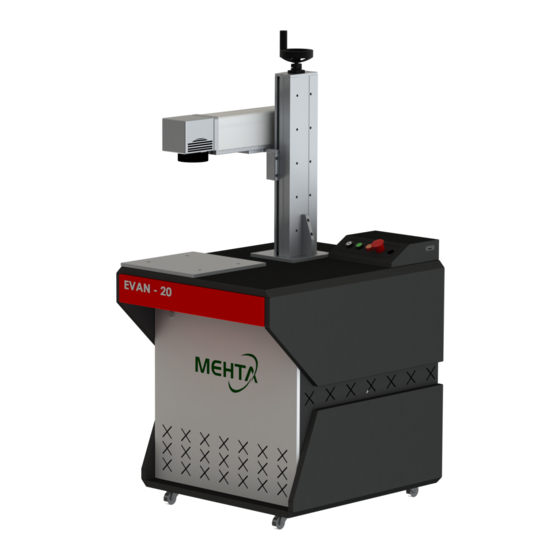
Page 11: Chapter 2 Structure Of Laser Marker Machines
Chapter 2 Structure of Laser marker Machines 2.1 Block diagram: 2.2 Economic type w w w. m e h t a i n d i a . c o m... -
Page 12: Panel Board
2.3 panel Board w w w. m e h t a i n d i a . c o m... -
Page 13: Chapter 3 Installation Of Machine
Make sure the device is properly grounded. No operator serviceable parts inside and all servicing should be done by qualified By MEHTA CAD CAM SYSTEM personnel. To prevent electrical shock, please do not remove covers. Any tampering of the product will void the warranty. -
Page 14: Method Of Installation
3.2 Method of installation Fix hard the module to the bracket, keep the laser in adequate ventilation. Connect the power line to 24VDC power and make sure enough DC output power is guaranteed. Pay attention to the polarity of the electric current: Phase =brown ; Neutral= blue ; Earthing = yellow and green power line definitions Fig:... -
Page 15: Chapter 4 Operation
Chapter 4. Operation 4.1 Pre-inspection 1. Make sure whether the device appears to be in good condition, the output fiber is bended or broken off. 2. Make sure signal line of laser and marking system are properly connected. 4.2 Operation procedures 1. -
Page 16: Chapter 5 Safety Precautions
Chapter 5 Safety Precautions The users should read the related operating manual carefully before operating. Must obey the operating regulations strictly. Non-trained people are forbidden to operate machine. The machine uses IV LASER (strong laser radiatation),this kind laser radiation might make following accidents: a. -
Page 17: Chapter 6 Breakdowns And Troubleshooting
Chapter 6 : Break Down And Trouble Shooting w w w. m e h t a i n d i a . c o m... -
Page 18: Chapter 7 Maintenance
Chapter 7 maintenance When the machine is not working ,it should be cut off from the machine and the computer power supply This machine does not work, the field lens cover, to prevent dust pollution of optical lenses. ... -
Page 19: Chapter 8 Application
Chapter 8 Application Auto Parts Hardware Watch & Clock Marking anodized & painted material Serial Numbers Manufactures Information Barcodes Logos Packaging Solar Industry Medical Device Marking Metal & Plastics ... -
Page 20: Software Section
SOFTWARE SECTION Chapter 1 Software Introduction 1.1 Software Installation The EzCad2 software run on an PC with 900 MHz CPU and 256 MB RAM at least. In general, we recommend the fastest PC available. EzCad2 was developed in Microsoft Windows XP and will run in Windows XP and VISTA ... - Page 21 Common vector images are supported. (ai, dxf, dst, plt…) Image processing (Grayscale, White / Black Transformations) Powerful hatching functions, such as support round hatch. More convenient IO operations and more easier to harmonize the auxiliary equipments. ...
-
Page 22: Installation Of The Software
1.3 Interface Introduction 1.3.1 Software starting interface The picture (Figure) appears while running the program, and meanwhile the initial operations takes place in the background . Fig : starting interface w w w. m e h t a i n d i a . c o m... -
Page 23: Main Interface
1.3.2 Main Interface w w w. m e h t a i n d i a . c o m... -
Page 24: Chapter 2 File Menu
Chapter 2 File Menu The File Menu is used for common file functions such as opening, saving, importing images from Twain equipment, etc. 2.1 New (N) “New" is used to create a blank work space to construct objects, and its shortcut key is “Ctrl+ N”. When “New”... - Page 25 2.2 Open (O) “Open” is used to load a saved “.ezd” file, and its shortcut key is “Ctrl + O”. When click “Open”, the software will pop an open-file dialog to ask you select the file you want to open, When you select a valid “.ezd” file, the dialog would display the preview of the file (you must have saved the preview when you save the file).
- Page 26 2.3 Save (S) / Save As (A) “Save” file is used to save the current state of a mark Document to disk. “Save As” is used to write the current mark Document to disk by another name. Writing a file to its current name is the same as the Save function. If the current Document has already been named, “Save”...
- Page 27 2.5 Obtain Scan Images (M) “Scan Images” is used to get digital graphic object from Twain device. When selected the “Scan Images” function will prompt the user to choose a Twain device. (The Twain device listed in the column should be those which have been legally installed in the computer.) When the suitable device is selected, you can now insert a graphic object into the currently selected Document.
- Page 28 Input IO mask: user could choose IO port through input IO mask, for example, if want to use IO 0,1,2,3, you can click 0,1,2,3. Output IO mask: user could choose IO port through output IO mask, for example, if want to use IO 0,1, you can click 0,1.
- Page 29 2.6.2 Color “Color” is used to set the color of background, work space, guide line and grid, etc. Double click the color stripe could change the color wanted. 2.6.3 Work Space The set of the work space’s property contains setting the size, type and position at the work space. The Work Space is the rectangle or circle area in the main interface window.
- Page 30 2.6.5 Move-Rotate Nudge Distance: the distance that the object moved when pressing direction keys each time. Big Nudge Scale: indicates the number the user wants to time the Nudge distance so as toachieve further each time when synchronously press direction keys and “shift” key together Rotate Angle: the angle the object rotates each time when press direction keys and “ctrl”...
- Page 31 2.6.6 Plug Manager The list displays the EzCad software plug which has already been installed in the computer. The users can activate or inactivate each plug. Press “blank” key or double click the plug name will switch the active state. Changes will take effect in EzCad’s next start.
- Page 32 2.6.7 User manager Uses in choosing whether to use the current software must to input the user password, as shown in Figure When enable “You must enter and password before using”, the system default has a administrator and a designer, the user can increase operator. The jurisdiction of administrator is to use software all functions The jurisdiction of designer is to revise all software function besides the user information The jurisdiction of draftsman is to draw file, set machine parameter, but can’t set user information,system...
- Page 33 2.6.8 Language This item is used to change languages between Chinese and English .Changes will take effect when restarting the marking software. 2.7 Recent File List Below the menu item of System Parameter, a list is displayed to show the latest Document files opened, and the max amount of the file items is ten.
- Page 34 2.10 Object Properties Object Properties are displayed in the left side of the main interface window X position: the X coordinate of the point in the left button corner of the object selected Y position: the Y coordinate of the point in the left button corner of the object selected Z position: the Z coordinate of selected object X Size: width of the object selected Y Size: height of the object selected...
- Page 35 Array: copy the current object and arrange them to the destination users want by setting the row column number and space Count X: the count of the row Count Y: the count of the column Inc (mm): the space between each row column. -set array’s row as marking precedence - set array towards vertical direction as marking precedence -Uni direction marking.
-
Page 36: Chapter 3 Edit Menu
Chapter 3 Edit Menu “Edit Menu” carries out the editing operation of an object. 3.1 Undo (U) / Redo (R) “Undo” will undo the last action that the user made in EzCad2. For example, if the user deleted an object accidentally, clicking Undo will bring the program back one step to where that item still existed. - Page 37 3.4 Group / Un Group When selected the “Group” function will keep the selected objects’ original properties and make them into a new object, and this new group, as the same as other object, can be selected, copied, pasted and set object properties.
- Page 38 For example: draw three rectangles, line distance is 1mm, angle is 0. 1. Do not click ‘All Calc’, system will mark as the order in object list, mark hatch line in the first rectangle then mark hatch line in the second rectangle, and so on. 2.
- Page 39 Optimization two-way hatch: similar with bidirectional hatch, but the end of each end connects Click the button will switch between the Uni direction, bidirectional, and ring like hatch. Fig: Types of hatch The left object is being filled by Unidirection Hatch or Bidirectional Hatch, the middle object by Ring-like hatch, and the right one is Optimization two-way Hatch) Optimization Gong type hatch: similar with Gong, will jump in null place.
- Page 40 Average distribute line: The solution the starting and ending hatch line are non-average distributes question when the object is hatched. After select this item, the software automatic adjust the hatch line space in the user setting hatch line space foundation, will let the hatch line average distribute. Line reduction: The hatch line both sides reduction.
-
Page 41: Chapter 4 Draw Menu
Chapter 4 Draw Menu “Draw Menu” consists of various common items for drawing, for instant, Dot, Line, Curve, Polygon, etc. Draw Menu has a Toolbar correspondingly, and all the operations can be achieved by pressing the icon on the Toolbar. For example, as Figure shows, when you have selected the drawing command or the icon in Toolbar, the Present Command Toolbar on the top of the main window will be changed to show some options of the current command. - Page 42 4.2 Curve To draw a curve, users can select command “Curve” in the Draw Menu or click the icon When command “Curve” selected, users can draw free curves by pressing the left button of the mouse and drag it. ...
- Page 43 4.3 Rectangle To draw a rectangle, users can select command “Rectangle” in Draw Menu or click the icon . Under the command “Rectangle”, users can press the left button of the mouse and drag it to draw a rectangle. Under the command “Rectangle”, users can draw a square by pressing the left button of the mouse and drawing it when press “Ctrl”...
- Page 44 4.4 Circle To draw a circle, users can select command “Circle” in the Draw Menu or click the icon Diameter: the diameter of the circle Starting Angle: the angle between the starting point and the centre of a circle : This figure refers to the drawing direction of the circle is clockwise. : This figure refers to the drawing direction of the circle is anticlockwise.
- Page 45 4.5 Text Typing text directly in the workspace is supported in EzCad2, and many types of fonts are supported. To type text, users can select command “Text” in the Draw Menu or click icon. Under the command “Text”, users can set up a starting point at any position wanted in the workspace to type characters by left click mouse.
- Page 46 Fig: True Type List Below dialogue box will be appear when we click this icon w w w. m e h t a i n d i a . c o m...
-
Page 47: Chapter 5 Marking
Chapter 5 Marking In EzCad2, every document file has 256 pens, 0 to 255 numbered, and they are located in the top of the Marking Properties Table. Each pen is corresponding to a group of marking parameter and the parameter base’s name is after the color. - Page 48 Manufactured &Marketes By: MEHTA CAD CAM SYSTEMS PVT.LTD. HEAD OFFICE: 4 & 5, 2 Floor, Sumel Complex, Opp.Gnfc Info Tower, Sarkhej –Gandhinagar Road, Ahmedabad-380059, India. Tel. : +91-79-26840551/ 26840552 /26840553 Fax : +91-26840554 Email : sales@mehtaindia.com www.mehtaindia.com Delhi | Mumbai| Bangalore | Jaipur | Raipur |Indore | Kolkata | Guwahati |Chennai...
- Page 49 Thank You w w w. m e h t a i n d i a . c o m...
Need help?
Do you have a question about the Evan Series and is the answer not in the manual?
Questions and answers